A brownfield is an oilfield whose production has matured to a plateau, or progressed to a declining stage. In brownfields, artificial lift methods are employed to add energy to the fluids inside a well, aiding their movement to the surface. This article overviews four popular artificial lift methods and discusses general screening criteria for selecting which method is the best for a specific well.
When is Artificial Lift Needed?
Improved oil recovery (IOR) methods are implemented to maintain production from brownfields (Darvish Sarvestani and Hadipour, 2019), prolonging their life cycles and maximizing oil recovery. Artificial lift (AL) refers to human-controlled means of increasing a well’s productivity, boosting its flow rate, while lowering the flowing bottomhole pressure (FBHP).
Well productivity depends on the use of compressional energy supplied by the reservoir, which declines with depletion. Two key relationships between FBHP and well flowrate are used to evaluate a production strategy (Fig. 1):
- The inflow performance relationship (IPR), which quantifies the flow from the reservoir in relation to the “drawdown” (difference between the average reservoir pressure and FBHP)
- The vertical lift performance (VLP), which quantifies the well’s flowrate in terms of the FBHP, depending primarily on the properties of the fluids present in the wellbore, along with the production tubing size.
The intersection between the IPR and VLP curves is called the “operating point” and is a measure of the well productivity. Absolute open flow potential (AOFP) refers to the maximum possible flowrate a well can deliver in the absence of any restrictions; if FBHP is reduced to atmospheric pressure.
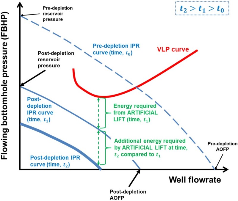
Fig. 1 displays a tick-shaped VLP (red) curve and three IPR curves; a dotted-blue for a reservoir at a “pre-depletion” scenario (at time, t0), where reservoir energy is sufficient for carrying fluids through the wellbore to the surface. The thinner solid-blue curve represents a “post-depletion” scenario (at time, t1), where AL is necessary to carry fluids from the reservoir to the surface. The green arrow indicates the FBHP drop required from the selected AL method to enable fluid flow to the surface.
Regardless of the selected AL method, adjustments are necessary for the output to continue matching the input available from the reservoir, throughout depletion. The solid-blue, post-depletion IPR curve will continue shifting throughout the well’s lifetime, moving downwards and to the left as the thicker solid-blue curve on Fig. 1 indicates, displaying the IPR curve at time, t2 (t2 > t1 > t0). Further depletion of a brownfield reservoir may even mandate switching to a different AL method.
Four Common Artificial Lift Methods: An Overview
Sucker-Rod Lift
Also known as “beam lift,” sucker-rod lift is the most classic AL method, employed in thousands of wells globally. Especially popular in stripper wells of minimal production (below 10 B/D), sucker-rod lift is usually the first choice for most onshore and even several offshore wells.
A downhole, positive-displacement pump is driven by a surface unit, with the flagship beam pump being the most widely used installation (Fig. 2a). Other less common types of reciprocating sucker-rod lift installations are also possible. A significant advantage of sucker-rod lift is that it can operate at very low FBHPs, yet its configuration contains multiple moving parts, which implies numerous reasons for maintenance (Bommer and Podio, 2012).
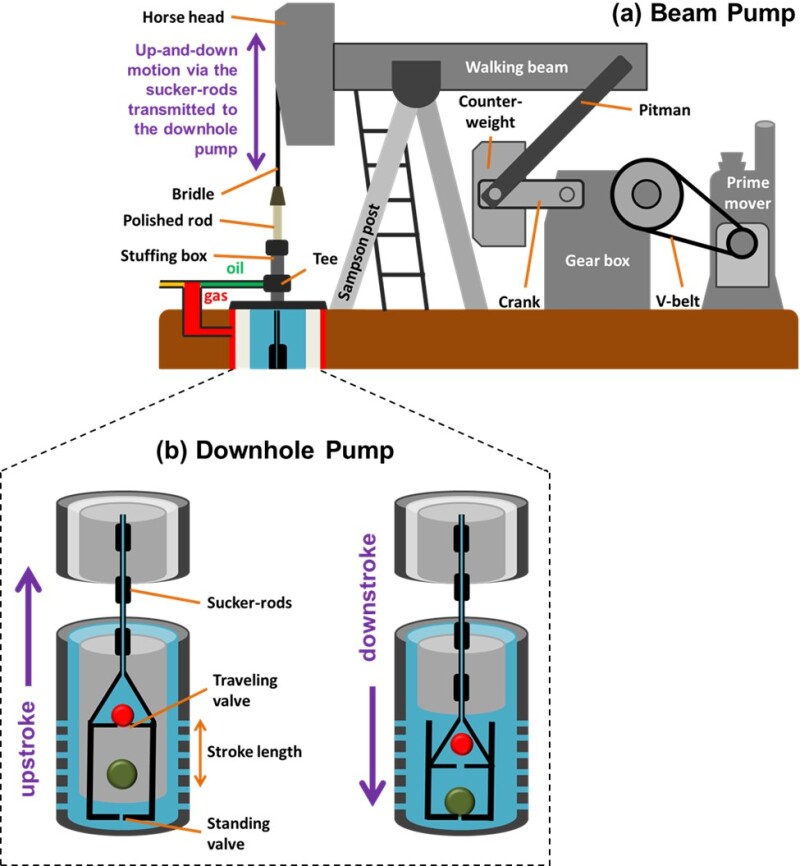
Beam pumps are driven by prime movers (can be motors or engines), through a gearbox with an attached crank mechanism at adjustable pumping speeds. The back-and-forth movement of the walking beam transmits up-and-down motion to the downhole components, through linked, steel sucker rods. Through this motion, the sucker rods activate the downhole pump, which operates through the dynamic status of two valves: The standing valve and the travelling valve (Fig. 2b). At every stroke, a volume of produced fluid is lifted through the sucker-rod tubing’s annulus and discharged to the surface.
Variations in the load against displacement experienced by the polished rod (Fig. 2a) over each stroke are recorded by a special instrument called the dynamometer. A dynamometer is an optional piece of equipment that can be used to take a snapshot of a well that performs abnormally. The shape of the survey recorded by the dynamometer is displayed on a dynagraph and can reveal problems affecting the equipment.
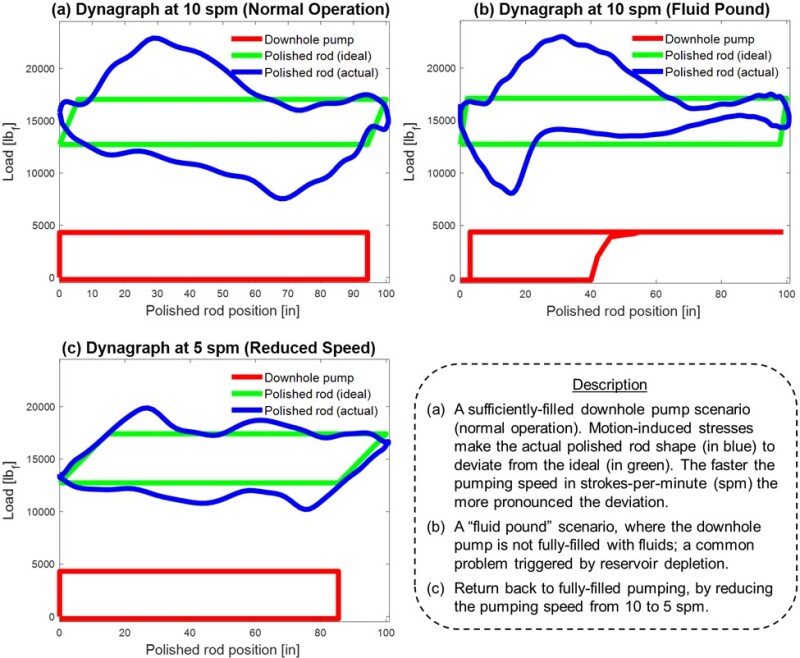
Figure 3 displays the signature shapes on dynagraphs regarding fluid pound—a common problem triggered by reservoir depletion where the downhole pump does not get sufficiently filled with fluids, and a simple remedy (Bommer and Podio, 2012).
Electric Submersible Pump (ESP)
An electric motor with the proportions of a slim fence post which stands on its head at the bottom of a well and kicks oil to the surface with its feet.
In 1911, the 18-year-old Russian, Armais Arutunoff (Fig. 4a) invented the first electric motor capable of operating under water. After immigrating to the US, he joined forces with Samual van Wert, a sucker-rod salesman, developing a prototype of an electric downhole multistage centrifugal pump used for driving fluid volumes upwards through the wellbore. ESPs have been employed extensively in more than 1,000 wells in the four manmade THUMS islands in Long Beach, California (Michael, 2019) aiding oil production from the Wilmington field (Fig. 4b), among many other places.
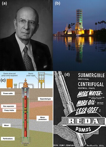
The ESP setup usually involves a tubing hung from the wellhead with a pump at the bottom of the tubing and a motor attached below the pump (Fig. 4c). Power is transmitted downhole to the motor through a three-phase power cable from a surface electric control panel. The motor shaft directly drives the pump.
The pump comprises a series of impeller-diffuser sets. The impeller creates high fluid velocity and the diffuser converts part of the induced kinetic energy into pressure. The higher the required discharge pressure is, the more impeller-diffuser sets are needed (limited by the maximum amount that the pump can carry). The available power in an ESP can be used to generate either a higher discharge pressure or a higher flow rate. Thus, each pump size has natural limits on pump flow rate and discharge pressure.
Due to its small surface footprint, ESPs are considered environmentally friendlier than other AL methods, such as sucker-rod lift. Arutunoff’s company, REDA Pumps (Fig. 4b) was by the end of the 20th century the world’s largest ESP manufacturer and now belongs to Schlumberger (Wallis, 2014).
Progressive Cavity Pump (PCP)
This method involves the use of a downhole positive displacement pump, which evolved from the helical gear pump concept, developed by René Moineau, an aviation pioneer in the 1930s (Cholet, 1997). Featuring low capital and running costs, strong reliability, and a small surface footprint, PCPs are becoming an increasingly popular AL solution.
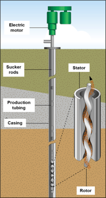
The helical, chromium-coated steel rotor and the elastomer-molded stator are aligned eccentrically at the bottom of the production tubing, creating fixed-sized pump cavities. As the rotor turns inside the stator, the rotating motion makes the pump cavities open and close, carrying fluids up through the wellbore in an orbital manner (Fig. 5).
A prime mover provides the motion from the surface, which is transmitted to the rotor through the wellhead using a sucker-rod string. Highly deviated wells often use a downhole motor, eliminating the need for a sucker-rod string, however in this application, ESP is the better choice (Table 1 later).
The elastomer stator can be a limiting factor on the pump depth or the discharge pressure, because as discharge pressure increases, the pump efficiency decreases. The rotating sucker rods can cause significant wear with the tubing should they come into contact.
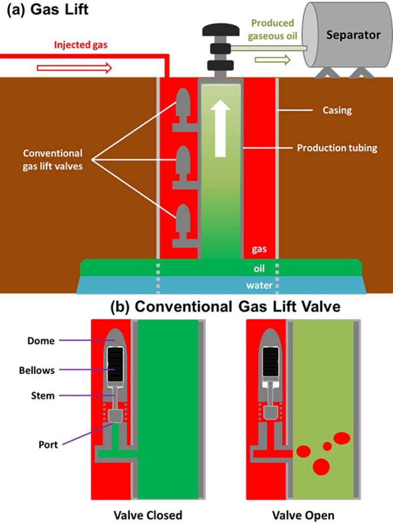
Gas Lift
This method involves intermittent or continuous injection of gas into a well through its annulus, which reduces the density of the fluids inside the wellbore, allowing the available FBHP to lift the mixture to the surface (Fig. 6a). The injection-gas can be supplied from nearby wells and gathered using a compressor. Conventional gas lift valves (Fig. 6b) are mounted onto mandrels on the production tubing, while wireline-retrievable gas lift valves are set onto side pocket mandrels.
Gas lift can be deployed over a wide range of well conditions as it can cope well with abrasive elements and sand production with low workover costs. Gas lift is especially popular offshore, along with onshore locations where a gas source is available.
For intermittent gas lift operations, an intermitter installed on the surface controls the gas injection timing, using fluid-operated valves, which open and close when the tubing pressure rises or falls, respectively, in relation to a threshold value. Alternatively, throttling-pressure valves are used, which open and close in response to casing pressure increase or decrease, respectively.
Selection Process and Well Screening Criteria
Several factors are considered when selecting the best AL method for a particular well. The AL selection process presents a discussion of the available AL methods in addition to the strengths and weaknesses of each method (Table 1) in relation to the existing well installation and reservoir (Neely et al., 1981; Temizel et al., 2020).

Despite AL selection being a multifaceted problem with unique challenges for each well, “expert programs” have been developed since the late-1980s in an effort to standardize and computerize AL method selection (e.g., Heinze et al., 1989). A sophisticated quantitative version of Table 1 is at the heart of any AL selection computer program. They incorporate workflows which consider user inputs for a well and its operating conditions to determine the most appropriate AL method. Modern data analysis techniques are becoming a popular avenue for further streamlining AL selection practices (e.g., Shi et al., 2018; Adam et al., 2022), with several workflows following economically guided techniques (Crnogorac et al., 2020; Nguyen, 2020).
Acknowledgement
Thanks to Distinguished Senior Lecturer Paul M. Bommer, at the Hildebrand Department of Petroleum and Geosystems Engineering at the University of Texas at Austin, for reviewing this article.
References
Bommer, P. M., and A. L. Podio. 2012. The Beam Lift Handbook. Petroleum Extension Service, Continuing and Innovative Education, University of Texas at Austin.
Adam, A. M., Mohamed Ali, A. A., Elsadig, A. A., et al. 2022. An Intelligent Selection Model for Optimum Artificial Lift Method Using Multiple Criteria Decision-Making Approach. In Offshore Technology Conference Asia. https://doi.org/10.4043/31482-MS
Cholet, H. (1997). Progressing Cavity Pumps. Editions Technip.
Crnogorac, M., Tanasijević, M., Danilović, D., et al. 2020. Selection of Artificial Lift Methods: A Brief Review and New Model Based on Fuzzy Logic. Energies, 13(7), 1758.
Darvish Sarvestani, A., and Hadipour, A. 2019. Artificial Lift Method Selection for Mature Oil Fields: A Case Study. In SPE Annual Caspian Technical Conference. https://doi.org/10.2118/198424-MS.
Heinze, L. R., Thornsberry, K., and Witt, L. D. 1989. AL: An Expert System for Selecting the Optimal Pumping Method. In SPE Production Operations Symposium. https://doi.org/10.2118/18872-MS.
Michael, A. (2019). The Past, Present, and Uncertain Future of California’s Oil Business. The Way Ahead.,.
Neely, B., Gipson, F., Clegg, J., et al. 1981. Selection of Artificial Lift Method. In SPE Annual Technical Conference and Exhibition. https://doi.org/10.2118/10337-MS.
Nguyen, T. 2020. Artificial Lift Selection Methodology for Vertical and Horizontal Wells in Conventional and Unconventional Reservoirs. In Artificial Lift Methods (pp. 317–347). Springer, Cham.
Shi, J., Han, Q., Ren, X., et al., 2018. The Application of Big Data Analysis in the Optimizing and Selecting Artificial Lift Methods. In SPE Middle East Artificial Lift Conference and Exhibition. https://doi.org/10.2118/192482-MS.
Temizel, C., Canbaz, C. H., Betancourt, D., et al. 2020. A Comprehensive Review and Optimization of Artificial Lift Methods in Unconventionals. In SPE Annual Technical Conference and Exhibition. https://doi.org/10.2118/201692-MS.
Wallis, M. (2014). Oil Man: The Story of Frank Phillips and the Birth of Phillips Petroleum. University of Oklahoma Press.