The life cycle of any conventional well is bound to decrease with time. Very few oil and gas wells produce uninterrupted from initial production to abandonment. There are many factors that hinder the continuous production of the well such as leaks, wear of tubulars, sensor failures, and pressure depreciations. Parts of the well will eventually require maintenance, repair, or even replacement. To perform this work, well intervention becomes a key.
This article provides a mirror between the past and the present of well intervention technologies.
Definition of Well Intervention
Several authors define well intervention as a means to gain access to a well with the goal to either repair, maintain, sense, replace equipment, or inject fluids. According to SPE, well intervention extends the life of a given well through providing access to stranded or additional hydrocarbon reserves.
There are two types of well interventions. The first is light well interventions, and the second is heavy well interventions. In a light well intervention, the operator lowers sensors or tools into a live well, while containing pressure at the surface. Heavy well interventions, also known as workovers, require the operator to kill the well before making major equipment changes. Heavy well interventions are usually completed to replace fatigued tubulars, tubing strings, and pumps that cannot be otherwise retrieved with light well interventions. Some heavy well intervention methods are performed with the intention to plug and abandon (P&A) a well or reconfigure a well to produce from a secondary zone.
Conveyance Methods
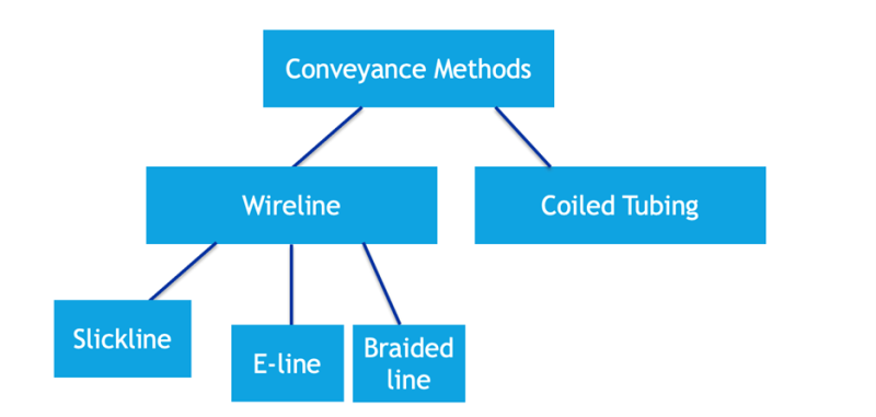
Operators perform light intervention using four main methods: slickline, braided line, e-line, or coiled tubing (CT). The light well intervention methods allow operators to clear the well from paraffins, sands, hydrates, and wax to ensure that the well is clear from blocked channels that have the potential to attenuate production. Operators may use light intervention methods to gather temperature and pressure data or to lower or adjust downhole equipment such as pumps or valves. Fig. 1 shows the different conveyance methods of light intervention.
Slickline, Braided Line, and E-line
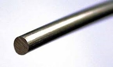
A slickline is a single strand of thin wire that transports sensors and tools into and out of the well. Slicklines look similar to the picture depicted in Fig. 2 and are reeled into a hydraulically driven drum. A slickline conveyance method is used for many applications, some of which include pulling plugs, pulling gas-lift valves, bailing sand and debris, bottomhole pressure and temperature surveys, and shifting sleeves.
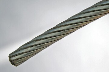
A braided line is a multiple-strand wireline as depicted in Fig. 3. Braided lines are more durable than slicklines and have a higher resistance to wear. When a larger size of braided line is used, killing the well might be necessary to avoid pressure surges caused by the large cross-sectional area of the braided line entering the wellbore. There are many uses for braided lines, some of which include deeper well access, conveying heavy tool spring, and fishing operations.
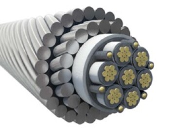
The third type of wireline conveyance method is the electric line (e-line) shown in Fig. 4. The e-line is a wireline system that provides real-time communication and measurements between the well (subsurface) and the surface. E-lines have many applications including unparallel depth control, logging measurements, zonal isolations, and well integrity.
Coiled Tubing (CT)
Coiled tubing is also a downhole conveyance tool used in well intervention as a conduit for fluids. It can vary in size ranging between 1 to 4 in. In general, most CT stings are made of low-carbon steel and can vary depending on their yield strengths.
There are many uses for CT such as washing out production-inhibiting sands or scales that have built up inside production tubing, or to perform acid stimulation treatment at precise locations within the well. Additionally, coiled tubing is used for fluid displacement, stimulation, perforations, fishing, logging, remedial cementing, and mechanical removal of blockage scales and paraffins. CT can also be used to transmit real-time data from subsurface to surface with the use of a downhole sensor. CT is also known to have a higher rigidity and structure; therefore, it can be used to push slickline, which typically depends on gravitational forces to move downhole in high-angle wells.
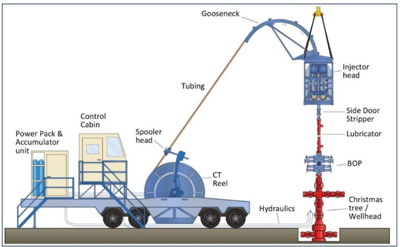
A CT unit comprises the following components: CT, control cabin, power pack, tubing reel, tubing guide (gooseneck), and injector head, all depicted in Fig. 5. In addition to the mentioned components, a CT unit contains a well-control apparatus that consists mainly of a blowout preventer (BOP) to isolate the pressure. Sometimes in CT operations, a nitrogen pump is used to cleanse the interior of the CT from any residual fluids. In such cases a nitrogen pumper is required on site. To ensure longevity of the CT life, the tubing guide (gooseneck) must have an arch radius at least 30 times the size of the tubing outer diameter (OD) and must withstand the loading caused by the reel-back tension.
There are many benefits to using CT including less wellsite preparation, ease of mobilization and rigging up, and reduction in downtime due to less tripping time. Other benefits include safe and high operational efficiency and cost effectiveness.
The main difference between a slickline and CT is that a slickline is a single strand of wire (not a tube), while CT is an actual hollow tube. CT has the ability to transmit fluids downhole while a slickline fails to do so.
Several chemical compositions can be used inside CT string, some of which include biocides, metal-to-metal friction reducers, hydraulic-friction reducers, inhibitors, H2S scavengers, and gels. Biocides are used to kill bacteria that could cause corrosion inside the CT, while metal-to-metal friction reducers are used to reduce the CT and casing friction. Hydraulic-friction reducers are used to decrease the pump pressure, while inhibitors and H2S scavengers are used to prevent excessive damage to the CT. Finally, gels are used to pump viscous slugs to aid with wellbore cleanup. One type of CT is active or real-time CT that works on measuring real-time downhole parameters. Other types include conventional CT which is made by welding flat strips of low-carbon alloy steel.
Increasing Intervention in Extended-Reach Wells (Tractors)
When dealing with horizontal extended-reach wells (ERWs), conventional well intervention conveyance methods such as CT lose their effectiveness. One of the root causes is helical buckling as shown in Fig. 6. Other challenges include increased frictional forces and high dogleg severity. To increase the intervention in ERWs, a CT tractor tool can be used.
Every tractor unit is made of the following components: electric components, motor and pump, wheel section, and a compensator. The electrics components control the motor and pump and are powered from the surface. The motor and pump generate hydraulic flow and pressure, while the wheel section provides axial force at the end of the wire. Finally, the compensator adjusts for oil pressure increases and keeps the pump primed.
Several research advancements have already been implemented such as the first worldwide deployment of slim-CT logging tractors. The tractor is unlike its predecessors. It provides real-time logging capabilities and aims to meet the demands of pulling the CT to a target depth. Slim CT was developed to meet the world’s demand in improving openhole coverage and ERWs logging jobs. The new logging tractor is the first slim tractor that has the ability to enable production logging operations in openhole horizontal ERW.

Future Downhole Robots
The future of well-intervention technology in the oil and gas industry is poised to be progressive due to economic needs and cost-reduction goals. Along with the advancements in technology and innovation, developing new tools, techniques, and approaches will improve the way well interventions are conducted.
A key aspect of the future of well-intervention technology is the increasing use of digitalization, data acquisition methods, and analytics. The industry is embracing digital solutions such as real-time monitoring to optimize well interventions which is helping with targeted interventions for efficient operation.
Automation of oil and gas operations became a top target during the Fourth Industrial Revolution, and numerous initiatives have been made to develop autonomous downhole tools, since traditional well-intervention techniques require production interruptions and significant crew and infrastructure deployment. Downhole robots, also known as downhole intervention robots, are the natural progression from tractors and pipeline-inspection robots that can potentially increase well intervention operational efficiency, safety, and cost-effectiveness.
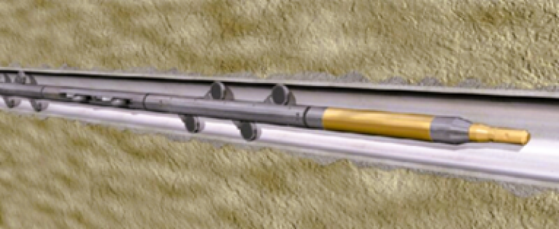
One of the key advantages of the expected downhole robots (Fig. 7) is their ability to access remote and rugged locations within the wellbore by navigating through narrow sections, deviated wellbores, and even complex completions, reaching areas that are difficult for conventional intervention techniques and reversing back to the surface without the need for human intervention. These robots could be equipped with sensors and tools to carry out complex operations including well logging, perforating services, cleaning, and selective stimulation. This capability while reducing the operations cost and time from conventional methods opens new possibilities for well interventions, improving overall well performance and recovery.
As downhole robot technology continues to advance, further enhancement and breakthrough is expected in their capabilities. Future developments may include improving the autonomous driving capabilities and enhancing the power management and storage systems to increase their operational time. Incorporating artificial intelligence and machine learning algorithms into these robots could enable self-decision-making and adaptive behavior, taking their operational efficiency to a new level.
Although downhole robots have a lot of potential, it's important to remember that obstacles could arise to their widespread adoption. To ensure their successful implementation, factors like reliability issues with harsh downhole environments and compatibility requirements with pre-existing well infrastructure must be taken into consideration. Downhole robots are nevertheless set to play a crucial role in the future of well interventions as the technology continues to develop and the energy industry keeps pushing the limits of innovation.
Conclusion
Well intervention is an important industry practice to enhance oil and gas production from depleted wells and is not only limited to the traditional methods, it is advancing to encompass downhole robots and autonomous intervention methods.
The oil and gas industry is abound with research opportunities and advancements related to the field of downhole well interventions; therefore, staying up-to-date is critical to understand the direction the industry is headed in.
For Further Reading
The Defining Series: Well Intervention—Maintenance and Repair, SLB.
Coiled Tubing Complete Guide, Drilling Manual.
Coiled Tubing Acidizing: An Innovative Well Intervention for Production Optimization by A. Khan, University of Engineering & Technology, Lahore, Pakistan, and M. Tauseef Raza, Eni Pakistan, International Journal of Engineering Research & Technology.
What is Coiled Tubing? Advantages, Equipment, and Common Operations, Oil and Gas Overview.
General Principles of Well Barriers by M. Khalifeh and A. Saasen and Kjølv Egenlands hus, Introduction to Permanent Plug and Abandonment of Wells. Part of the Springer Ocean Engineering & Oceanography book series.
Coiled Tubing BOP and Pressure Control Equipment Guide, Drilling Manual.
Production Logging, PetroWiki.
Extending the Reach in Horizontal, Deviated Wells Can Recover More Reserves, Offshore Magazine.
The Development of Wireline-Tractor Technology by B. Schwanitz, et. al, JPT.
Improved System for Accessing Multilateral Wells in Canada by B. Harber, J. Stuker, and D. Pipchuk, SLB.
How Do Well Tractors Work? Rigzone.
Discovery MLT, SLB.
Tubing Design Criteria, Rig Worker.


