
This article provides an overview of risk-based measurement, monitoring, and verification (MMV) for efficient, long-term CO2 storage. MMV is a regulatory requirement to gain and maintain a storage permit (where CCS regulations exist). It delivers the data needed for demonstrating that the injected CO2 behaves as expected and initiates timely corrective measures in the unlikely event of an irregularity. The MMV method is explained including the underlying risk framework and the process is illustrated with some operational examples from the Quest CCS facility operating at the hydrogen manufacturing units of the heavy-oil upgrader at Scotford, Alberta.
Carbon capture and storage (CCS) is a critical technology solution to achieve net zero ambitions targeted by countries and industry alike. This requires deploying CCS at gigaton scale and ensuring that CO2 injected into the subsurface remains permanently in the ground as intended.
To establish technical CO2 storage site feasibility, a comprehensive characterization of the subsurface is required. This includes the geosphere, hydrosphere, biosphere, and all wells in the area which could potentially be affected. All credible subsurface risks which threaten the long-term security of the CO2 storage site must be assessed and managed to ALARP (i.e., the residual risks shall be reduced as far as reasonably practicable).
An accepted industry approach is to use the bowtie method and leakage scenario thinking for this purpose (De Ruijter, Guldenmund 2014). This in turn is the basis for the development of a site-specific MMV program (Bourne et al. 2014; Dean and Tucker 2017).
Industry guidance on MMV has been published by the International Association of Oil & Gas Producers (IOGP) in Recommended Practices for MMV and by regulators in several countries. For example, MMV guidelines by the Alberta Energy Regular are incorporated in Directive 065; guidance on monitoring and corrective measures by the European Commission are in Guidance Document 2; and the UK’s North Sea Transition Authority has published a report on Offshore Monitoring for CCS considering challenges related to co-location such as windfarms. The World Resources Institute published CCS guidelines which include MMV.
MMV Method
Site selection, characterization, and engineering designs are considered the prime means of ensuring confidence in the long-term security of a CO2 storage site. A CO2 storage operator demonstrates that a site is performing as expected using a site-specific, risk-based MMV plan. The goals of MMV can be split into the three Cs: containment, conformance, and confidence.
MMV Goals
MMV provides the necessary data to verify containment, demonstrate conformance, and to fulfill regulatory obligations.
1) Containment: MMV data either provide stakeholders with evidence of absence of loss of containment or trigger timely controls. Contingency monitoring may be required to inform corrective measures.
2) Conformance: History matched forward models can correctly predict MMV data, thereby demonstrating that the operator understands the long-term behavior of the CO2 and pressure plumes.
3) Confidence: MMV data demonstrate to regulator and other stakeholders that the CO2 storage site behaves as predicted and the license to operate is maintained. After storage closure, MMV is critical to enable the handover of the site back to the responsible authority.
Well-established industry practices for well and reservoir management and environmental monitoring provide the key capabilities to fulfill these requirements. CO2 storage regulation requires comprehensive coverage of temporal and spatial monitoring domains, including wells, the geosphere, the hydrosphere, and the biosphere. All temporal monitoring technologies must have a baseline acquisition period to establish what is normal followed by injection and post-injection monitoring to prepare for handover to the government.
Bowtie Risk Assessment
The MMV design process starts by evaluating site-specific storage risks using the bowtie method. It provides a framework for a systematic risk assessment of events with the potential to affect storage performance. The bowtie (Fig. 1) represents the relationships between the five key elements: top event, threats, consequences, preventive safeguards, and corrective safeguards.
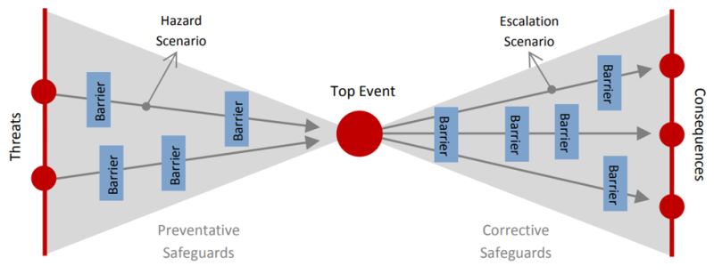
The top event is the unwanted event placed in the center of the bowtie (i.e., the realization of a hazard); for example, movement of the CO2 plume outside the storage complex. The threats are possible mechanisms that could lead to the top event; for example, a permeable fault or fracture system, injection-related stresses (pressure or thermal), or poorly plugged abandoned wells. The consequences are the possible adverse outcomes from the unexpected occurrence of the top event; for example, CO2 or brine migration to the underground source of drinking water impacting the quality of drinking water.
Preventive safeguards (or barriers) decrease the likelihood of a threat leading to a top event in a hazard escalation scenario. Corrective safeguards (or barriers) reduce the severity of consequences in an escalation scenario after the top event occurs.
Both sides can have passive and active barriers. Passive barriers are either geological or engineered. For example, during site selection, geological safeguards such as seals (shale, salt) are selected to prevent migration of CO2 outside the intended storage location. Other safeguards are engineered, like holding the CO2 injection pressure well below the formation fracturing pressure or designing an injection well to be corrosion resistant. Active barriers comprise a sensor (monitoring technology), a decision logic (this includes processing, interpretation, and defining suitable threshold for detection), and corrective measures (reducing injection rate, switching injector, etc.).
MMV Design
MMV is regulatory-compliant, risk-based, site-specific, and adaptive. These principles guide the design process that identifies the monitoring tasks and the respective technologies needed to reduce storage risks to ALARP. A stepwise approach is taken.
- Step 1 is to assess the site-specific storage risks by establishing definitions for loss of conformance and loss of containment, defining top events, and identifying potential threats and consequences using the bowtie method. This includes both geological and well-related risks.
- Step 2 assesses the geological safeguards by identifying and appraising the integrity of geological seals, faults, and escape features within and above the storage complex.
- Step 3 identifies and assesses engineering concepts that safeguard against all credible well and geological threats.
- Step 4 evaluates these initial safeguards (from Step 2 and 3) by determining their expected efficacy in relation to the identified conformance and containment threats and their potential consequences.
- Steps 5 and 6 consider monitoring. First, the monitoring tasks required to verify the performance of the initial safeguards are defined. Then, monitoring technologies are selected by considering leak-path scenarios and according to a cost-benefit ranking. The benefits are judged on how effective each technology is at each task, including baseline monitoring and monitoring during the injection and closure phases.
- Step 7 identifies contingency monitoring by developing alternative monitoring plans to investigate suspected irregularities and establish clear criteria for when and how to implement these contingencies. The results of the contingency monitoring inform the corrective measures.
With time, monitoring data and updated models aligned with the acquired data reflect a deeper understanding of the storage site, and conformance can be demonstrated. Generally, regulators request regular updates to MMV programs in alignment with the most recent understanding of the storage site risks. This provides opportunities to reduce or increase the MMV scope and to deploy more efficient technologies.
Operational MMV—The Quest CCS Facility
The Quest CCS facility separates, captures, and permanently stores CO2 from the hydrogen manufacturing units at the heavy-oil upgrader at Scotford, Alberta, thereby reducing greenhouse gas emissions.
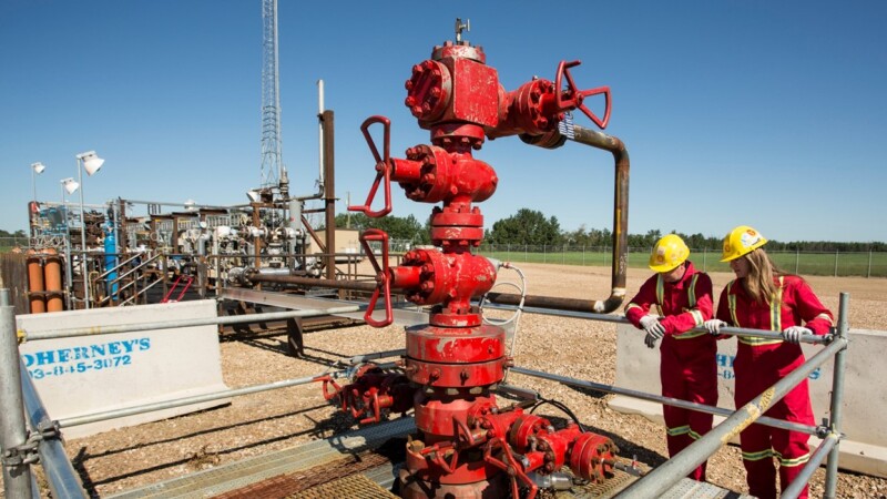
The capture method is based on licensed Shell technology using an ADIP-X amine solvent system. The captured CO2 is then transported via pipeline to the injection wells located about 50 km north of Scotford (Fig. 2).
There are three injection wells which inject more than 1 Mt/y of CO2 into the Basal Cambrian Sandstone unit, a formation at about 2 km depth, for permanent storage. Since 2015, the project has successfully stored more than 8 Mt of CO2, and the injectivity has significantly surpassed expectations.
Through a comprehensive MMV program, a broad range of valuable monitoring data has been collected to demonstrate conformance and containment. The monitoring technologies include atmospheric CO2 monitoring using LightSource technology (Hirst et al. 2017). The technology was successfully field tested with a controlled release experiment before injection.
No CO2 emissions have been detected from the storage site. Other monitoring technologies including groundwater sampling, subsurface geophysical methods, and in-well fiber-optic monitoring (Harvey et al. 2022) also confirm containment. Fiber-optic in-well sensing is lower cost compared with traditional 4D surface seismic methods for conformance and containment monitoring near the wells. It records time-lapse, distributed-acoustic-sensing (DAS), vertical-seismic-profiling (VSP) data. At Quest, this technology was successfully demonstrated as fit-for-purpose to image the plume up to 1 km away from the wellbore (Fig. 3).

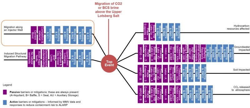
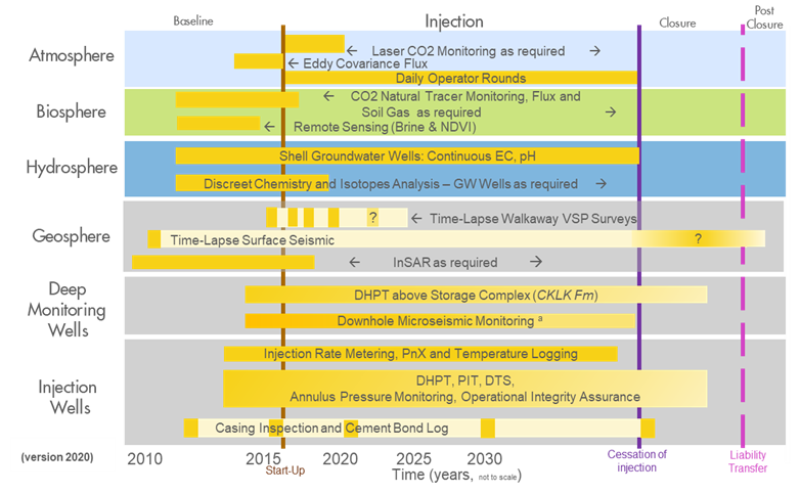
As an early CCS facility, Quest was initially designed conservatively, which resulted in an MMV program that was comprehensive. The design principles mean that the monitoring plan is updated regularly and reflects the increasing confidence in the storage performance based on operational data. Consequently, fewer measurements are required, and some technologies have been removed. Figs. 4 and 5 show the updated bowtie and MMV plan after 5 years of operation.
For Further Reading
Bourne, S, Crouch, S, Smith, M. 2014. A Risk-based Framework for Measurement, Monitoring, and Verification of the Quest CCS Project, Alberta, Canada. International Journal of Greenhouse Gas Control.
Dean, M, Tucker, O. 2017. A Risk-based Framework for Measurement, Monitoring, and Verification (MMV) of the Goldeneye Storage Complex for the Peterhead CCS Project, UK. International Journal of Greenhouse Gas Control.
De Ruijter, A, Guldenmund, F. 2014. The Bowtie Method: A Review. Safety Science.
Harvey, S, Hopkins, J, Kuehl, H, O’Brien, S, Mateeva, A. 2022. Quest CCS Facility: Time-lapse Seismic Campaigns. International Journal of Greenhouse Gas Control.
Hirst, B, Randell, D, Jones, M, Jonathan, P, King, B, and Dean, M. 2017. A New Technique for Monitoring the Atmosphere Above Onshore Carbon Capture and Storage Projects That Can Estimate the Locations and Mass Emission Rates of Detected Sources. Energy Procedia.

Marcella Dean has over 20 years of experience as a geophysicist in the oil and gas industry and is currently employed by Shell Global Solutions International. She is leading a subsurface specialist team responsible for developing the next generation of technologies to ensure safe and efficient CO2 and H2 storage. Prior to this role she was responsible for the development of state-of-the art geophysical and environmental monitoring technologies to verify the containment of injected fluids. She is known as one of Shell’s main experts in risk-based Measurement, Monitoring, and Verification (MMV) for CO2 storage. Dean was raised in Switzerland, studied and worked in New Orleans, Brunei, and the Netherlands.

Simon O’Brien is the Global CCS Deployment Lead at Shell, leading or supporting the delivery of CCS projects around the world. He is responsible for storage exploration and appraisal, technical assurance, integration, technology maturation, helping to shape the CCS research agenda, and the development of competences and capacity within Shell. Prior to this role, he spent 6 years as the Quest Subsurface Manager, overseeing the storage aspects of the Quest CCS project at the Scotford Upgrader in Canada, focusing on getting the facility up and running and ensuring smooth commercial operations.
O’Brien is a geophysicist with BSc and PhD degrees from Memorial University of Newfoundland and an MSc from the University of British Columbia. He joined Shell in 1997 and worked in seismic processing, depth imaging, quantitative interpretation, and new technology development for almost 20 years before working with Quest. His work has included a wide variety of projects; structural and stratigraphic, conventional and unconventional, onshore and offshore, hydrocarbon, and CCS in a wide range of countries around the world.