This is the third and final article of the field development plan (FDP) series tailored for petroleum undergraduate students and early-career professionals.
The first part provided insights into geology and geophysics, petrophysics, and reservoir engineering. The second part centered around drilling and production engineering.
The third part focuses on the facility engineering and petroleum economics aspects of a FDP. Facility engineering determines platform processing requirements and guides the design of midstream options, representing a significant portion of the overall FDP cost. Petroleum economics evaluates project profitability, ensuring the FDP is both technically viable and commercially sound.
Facilities Engineering
In facilities engineering, the main elements discussed are the available midstream options, such as tankers and pipelines, pipeline design, and surface facilities required for oil processing. Facilities engineering can be divided into three categories: onshore, deepwater offshore, and shallow-water offshore.
Onshore: The development concept is based on the usage of well pads. In general, for onshore facilities engineering, there are three categories.
- Well pad group to the main production facilities
- Multiple well pad groups to the main production facilities
- Multiple well pad groups with a manifold to the main production facilities
The well pad is designated with square boxes on which wells are drilled, and oil is produced. The well pad should have multiple wells, where, in a bigger reservoir, multiple well pads are common, especially if the oil-bearing zones are scattered in the reservoir. The produced oil from the well pads can either be sent to the main production facilities directly or gathered in a manifold and then sent to the main production facilities.
Unlike offshore development options, where the water depth has much control over the costs, onshore development options depend on the terrain, where different terrains have different costs. The more hardship is incurred in the development, the larger the costs. In terms of midstream transportation for onshore development, the oil will be sent to either a terminal (inland or coastal) or to a pipeline system.
Deepwater: Options are selected based on water depth, reservoir characterization, and project economics.
- Floating production storage and offloading (FPSO) vessels with subsea tieback
- Compliant tower
- Tension leg platform (TLP)/spar buoy
An FPSO is a main tanker, equipped with processing capability, used in deepwater operations. Oil produced from a subsea well is sent to an FPSO, where the vessel processes the oil and gas before offloading it to a shuttle vessel, or in some cases, sending it to a pipeline or other downstream facility.
For a deepwater operation up to 3,000 ft of water depth, a compliant tower can be used. For a depth limit of 7,000 ft and 10,000 ft, TLP and spar platform can be used, respectively.
Shallow water: Platform-based development (Fig. 1) is the most common method implemented with different combinations and midstream options such as:
- Centralized processing platform (CPP) with pipeline
- CPP with floating storage offloading (FSO) vessel
- Unmanned/satellite/wellhead platform with CPP (no tieback)
- Tieback (contingency option)
A CPP is a processing platform that is typically paired with either an FSO or a pipeline, both of which gnerally have no processing capability. In a tieback development, an unmanned platform is connected to an existing CPP. The operator of the tiebacked-in field may pay a tariff or processing fee to the CPP operator.

An FSO is a tanker used to store and offload oil and has no processing capability, so it is typically paired with an existing processing facility such as a CPP. These tankers are usually contracted on a day-rate or charter basis. They can transport the oil on their own or to a pipeline.
An FPSO is a less common in shallow water unless the field is in a very remote location.
Surface equipment under facilities engineering includes separators, compressors and pumps, depending on the type of fluids handled, and special equipment to treat sour gas if significant, such as an acid-gas removal unit.
Vertical separators save space on platforms, while horizontal separators handle high flow rates more efficiently due to their longer liquid travel path, which improves separation. Multistage separators maximize liquid recovery and to handle high-pressue inlet streams.
The next step is pipeline design, which determines the required inlet pressure from the platform for the oil to be transported to the shore. The inputs needed for pipeline design include the length of the pipeline (distance from the platform to shore), assuming there is no tortuous terrain, the pipeline roughness, the elevation survey, expected outlet pressure, daily liquid flow rate, and temperature.
Fig. 2 shows an elevation survey that details the path of the pipeline from the platform to shore. A unique convention for the survey is the signage, where the negative is above sea level, and below the sea level is positive. However, this elevation survey is simplified—particularly where the pipeline returns to shore. In reality, this section would show a gradual incline rather than a straight vertical rise.
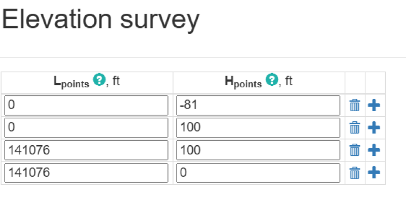
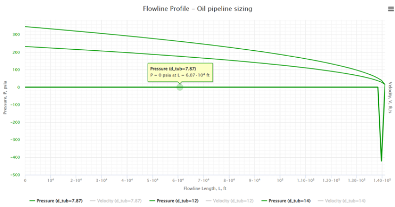
Fig. 3 shows an illustration of the output of the pipeline design, where three inside diameters were tested—7.87-in. (default), 12-in., and 14-in. pipelines. Based on the plots, 7.87-in. pipeline failed to deliver the liquid to shore, while both 12- and 14-in. pipelines successfully delivered the liquid. However, 12-in. pipeline required an inlet pressure around 345 psi, while 14-in. only required 232 psi. Since a 12-in. pipeline requires higher inlet pressure, a pump/compressor might be necessary to enable flow. On the other hand, 14-in. pipeline requires less pressure but costs more due to the greater material volume for its larger diameter. The selection depends on the cost-effectiveness of both options.
Petroleum Economics
The penultimate section of the FDP is petroleum economics. The first part of economics is the cost of the project, which can be divided into capital expenditure (CAPEX) and operating expenditure (OPEX). Among the major components of the CAPEX are the wells drilled, the pipeline, and the platform. The OPEX consists of the personnel cost to perform work during the entire production period and includes mainly maintenance operations.
The stage after cost modeling is the revenue computation by using the global price of hydrocarbons. Profitability, on the other hand, is dependent on the tax mechanism and contracts that vary from region to region.
There are three common profitability indexes: net present value (NPV), internal rate of return (IRR), and the payback period (breakeven). Any proposed engineering project must be evaluated from an engineering economics point of view, especially upstream projects, which span numerous years. A project that takes place over many years is subject to high uncertainty, especially in terms of the time value of money. A discounting factor will be applied, changing the net cash flow (NCF) to NPV. Having a positive NPV is not the ultimate greenlight for the project, as the risks of the project must be analyzed using the IRR method. If the IRR computed is more than the minimum acceptable rate of return or the hurdle rate, then the project is good to go. Finally, a project that yields an earlier payback period is always preferable.
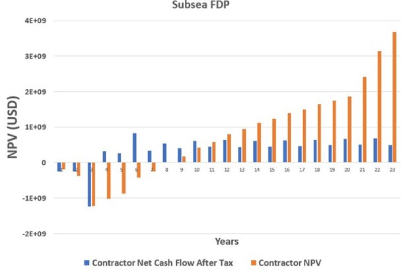
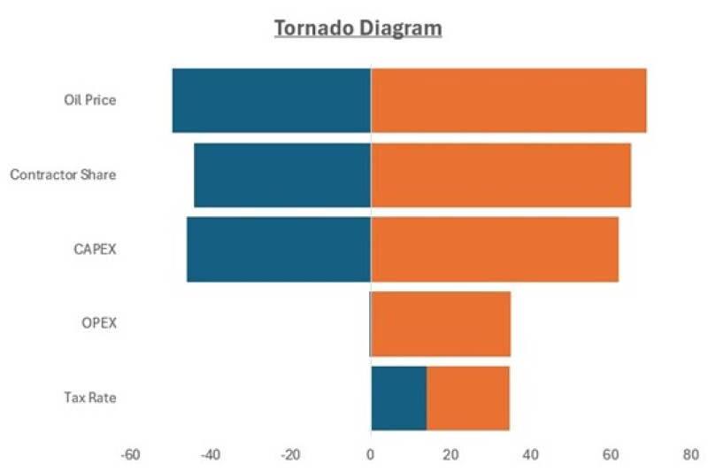
The last section of petroleum economics is the sensitivity analysis, where the fiscal terms, hydrocarbon price, and costs are varied and the impact on the profitability indices is observed. Sensitivity analysis can be shown using a spider plot or tornado diagram. Figs. 4 and 5 show examples of NCF+NPV and a tornado diagram, respectively.
The snapshot below shows a post-training photo of the author engaging with Universiti Malaysia Sabah students and lecturers, the 2-day FDP training comprised facilities engineering and petroleum economics.