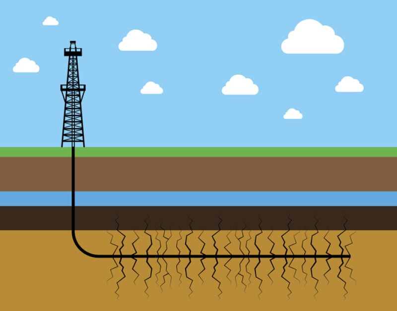
Hydraulic fracturing is a well stimulation technique involving high-pressure fluid and proppants to crack the rock and keep induced fractures open, thereby creating high-conductivity channels in a low-permeability reservoir to improve the flow rates of hydrocarbons.
This article provides an overview of hydraulic fracturing operations and on-site activities of a fracturing engineer. The goal is to give petroleum engineers early in their careers a comprehensive and accessible look into modern fracturing practices.
Fracturing Operations
Stage 1: Target reservoir of the well is perforated. Diluted hydrochloric acid is pumped initially to clean the debris and to initiate the tiny flow channels near the wellbore.
Stage 2: This is followed by pad fluid which is pumped at high pressure to open the fractures in the rock without immediately filling up with the sand. During the beginning of this stage, the well is opened, the ball is dropped. Once the ball sits in the plug, rate is kept steady and the formation breakdown pressure is observed. Once we know the formation is broken, the rate is increased as per the design.
Stage 3: Once the fractures are initiated, proppant-laden fluid is pumped to extend the fractures and deposit the proppant. Multiple substages with increasing sand concentrations will be pumped. Once the desired treatment pressure and rate is achieved, slurry steps start with lower sand concentration. In some instances, a small sand slug is pumped to analyze whether the formation takes the proppant. If the treating pressure is good, proppant concentration is increased as per the design, and designed volume is pumped.
Stage 4: Once the designed volume is pumped, well is flushed to clear the additional proppant in the wellbore. Once the stage is completed, instant shut-in pressure is measured to calculate the fracture gradient. The well is handed over to the wireline. Wireline runs into the hole with the perforating guns and bridge plugs. Bridge plugs are used to isolate the stages.
Once the plug is set and shots are fired in the next planned interval and confirmation is received, the wireline is pulled out of the well and the well is handed over to the fracturing crew for stimulation of the next stage. In horizontal wells, the process is repeated.
Stage Monitoring
During stimulation, engineers monitor pressures and rates with downhole gauges to assess fracture performance.
Formation breakdown pressure: A sudden increase in pressure followed by a sharp drop indicates that the formation has been successfully broken down, initiating fracture propagation.
Stable pressure trends: Consistent treating pressure suggests steady fracture growth and effective proppant placement. Fluctuations may indicate issues such as screenouts or fluid loss.
Pressure declines post-injection: Monitoring the pressure decline after stopping injection helps determine the instantaneous shut-in pressure (ISIP), which is used to estimate fracture closure pressure and evaluate fracture efficiency.
Injection rate increases: Gradual increases in injection rate are used to control fracture growth and prevent sudden pressure spikes that could lead to screenouts.
Injection rate drops: Unexpected drops in injection rate may signal equipment issues, fluid leakoff, or formation anomalies. Immediate investigation is required to address these challenges.
Integrated analysis of both injection rate and pressure can help determine fracture complexities, treatment design optimization, and ensure operational safety.
Flowback post-hydraulic fracturing: Once the fracturing is completed, the well is shut for a certain time frame, plugs are drilled by coiled tubing unit, and the well is put on the flowback where the injected fluids return to the surface and initial oil or gas is produced. Flowback recovery ranges from 20 to 50% and the rest remains in the formation or is slowly produced over time.
Flowback recovery after hydraulic fracturing is inherently limited by a convergence of reservoir engineering factors like capillary pressure-driven imbibition and relative permeability hysteresis in ultratight pores. Rock-fluid interactions (like wettability and clay swelling) further trap fluid and can damage conductivity. The pressure gradients available during flowback are typically insufficient to overcome capillary forces and dislodge all the imbibed water, especially given operational constraints on how fast a well is opened. Fracture network characteristics, including any fracture closures and the complexity of the fracture system, provide numerous pockets where fluid can reside without a clear path back to the well.
These technical factors mean that recovering only 20 to 50% of the fracture fluid is normal. The remaining 50 to 80% of the fluid stays in the reservoir, either harmlessly trapped or sometimes contributing to formation damage (like water blocking) that can impede hydrocarbon flow. Low flowback efficiency is a result of complex multiphase flow interactions in unconventional reservoir conditions, as supported by both laboratory studies and field observations.
The stimulation procedure is designed by completion engineers. Parameters like pump rate, fluid viscosity, and total volume are modeled using software to achieve desired fracture geometry while avoiding unwanted propagation. A good stimulation job will result in a network of fractures which are held open by proppant, significantly improving the wells connectivity to the reservoir. Vertical well designs vary from 1 to 6 stages, while horizontal well designs vary from 20 to 70 stages depending upon the formation and basin.
Daybreak of a Fracture/Field/Stimulation Engineer
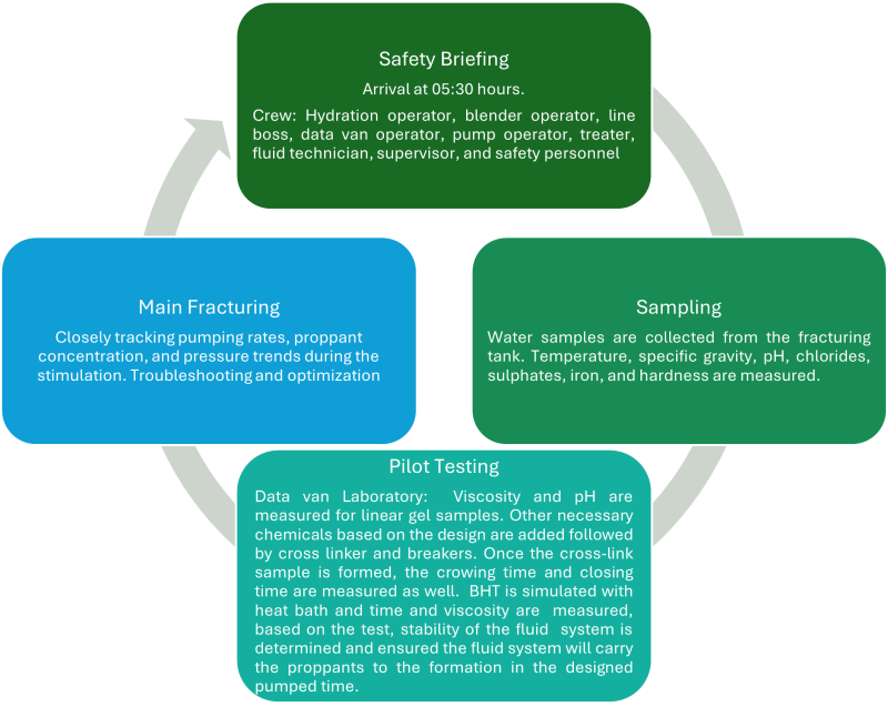
Troubleshooting
There can be instances where the samples are not crosslinking; this could be identified and fixed by one-to-one process analysis. If the fluid breaks before the designed pump time, the concentration of chemicals is varied, and the test is repeated to determine the stable fluid system. In one instance, chlorine dioxide concentration was increased in a water treatment line which led to weak crosslink samples. This was found by running a quick pilot test which saved nonproductive time on the wellsite.
In another example, samples were good in the beginning stages, but in one stage the sample broke quickly. The viscosity was good in the hydration unit and pH was good as well but the sample in the blender tub had low pH. It was found that the acid line was not closed properly, resulting in acid trap which weakened the crosslink sample and reduced the pH. Also, in main fracturing, consistent pressure trends and stable pump rates typically indicate effective fracture propagation and proppant placement. Conversely, sudden variations in treating pressure or unexpected drops in injection rate have alerted the team to issues such as potential screenouts or fluid leakoff, enabling us to immediately adjust to restore optimal conditions.
Conclusion
Hydraulic fracturing has evolved into highly sophisticated operation at the intersection of geology and engineering. For early career petroleum engineers, mastering hydraulic fracturing is fundamental—it is often the make-or-break factor in the success of unconventional wells. It means not only understanding technical mechanics but also the operational coordination. Real-world case studies have shown effective fracturing can dramatically increase wells output, whereas problems like screenouts or poor coverage can stunt a well’s potential. Hydraulic fracturing is a dynamic field where operations and equipment are continuously improving.
Part 2 of the article series will focus on procurement in fracturing operations and advancements in the fracturing equipment.