Carbon capture and storage (CCS) is a crucial tool to combat climate change. Any potential subsurface location for carbon dioxide (CO2) storage must meet the benchmarks that warrant effective, safe, and economic storage functions.
This article identifies the most suitable underground site for storing captured CO2 which is a necessary part of the CCS sequence of activities.
Decisive Factors for Geological CO2 Storage (GCS) Site Selection
The International Energy Agency (IEA) estimates a ninefold increase in global carbon storage capacity by the end of 2030. One of the vital features in the CCS process is the selection of a fitting site for the geological storage of CO2 (Alcalde, et al., 2021).
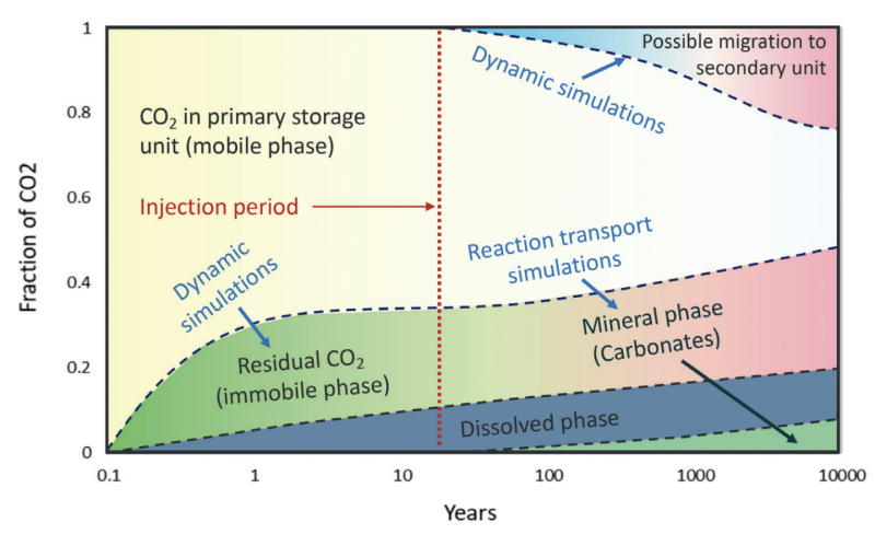
An appropriate site should assure the safe, sustainable, and economic storage of CO2 over geological timescales as seen in Fig. 1 (Ringrose, et al., 2022).
This brings us to one of the burning questions in the realm of CCS, what makes an ideal site for CO2 storage? To find that answer, we need to look at a few more questions.
How Do We Store CO2 Underground?
The fundamental idea is to store captured CO2 underground in reservoirs that would otherwise contain a mixture of water, oil, and/or gas. But we are not essentially putting back what we took out, since molecular mass of methane (CH4) is 16.04 g/mol whereas for CO2 it is 44.01 g/mol (Ringrose, et al., 2022).
Density and viscosity of CO2 varies highly with pressure and temperature. To ensure that it is stored in a dense form or the super-critical phase, the storage site usually needs to be deeper than 800 m. Greater depths also conform to storage security, as these are places where natural gas has been trapped for millions of years.
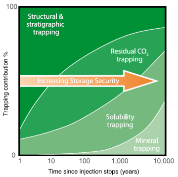
Trapping mechanisms of injected CO2 involve both physical and geochemical factors. The four basic mechanisms for trapping injected CO2 are shown in Fig. 2 and discussed below.
Structural and Stratigraphic Trapping
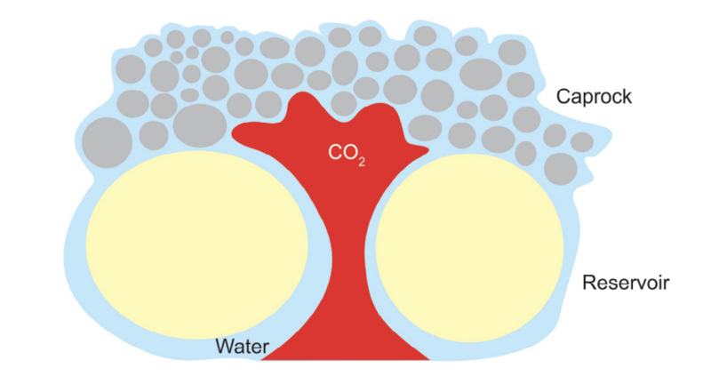
A homogeneous GCS site with just a tight caprock might not be sufficient. Every caprock will have a capillary entry pressure at which CO2 will eventually move through and into the shallow subsurface (Fig. 3). The thicker the CO2 column, the higher the buoyancy force on the caprock and greater the risk of reaching the capillary entry pressure. Factors like grain size, pore throat diameter, lateral extension, absence of natural fractures, high fracture pressures can reduce the demand on the caprock and thereby lessen the risk of CO2 leaking through it. A combination of structural and stratigraphic traps provides a more robust system that can prevent the injected CO2 from escaping.
The spill point (the deepest point in a trap that can hold hydrocarbon) of stored CO2 is shallower than oil or gas due to the interplay between buoyancy and capillarity. The goal is to retain the injected CO2 for thousands of years in the subsurface.
While heterogeneity might be a constraint to producing hydrocarbons, it is favored in an ideal GCS site (Bump, et al., 2023). Increasing heterogeneity in the storage site would enable trapping of CO2 below the spill point and thereby reduce the stress on the top seal. But, at the same time heterogeneity can reduce the storativity or capacity of the reservoir, increase the injection pressure, and decrease injection rates.
Residual CO2 Trapping
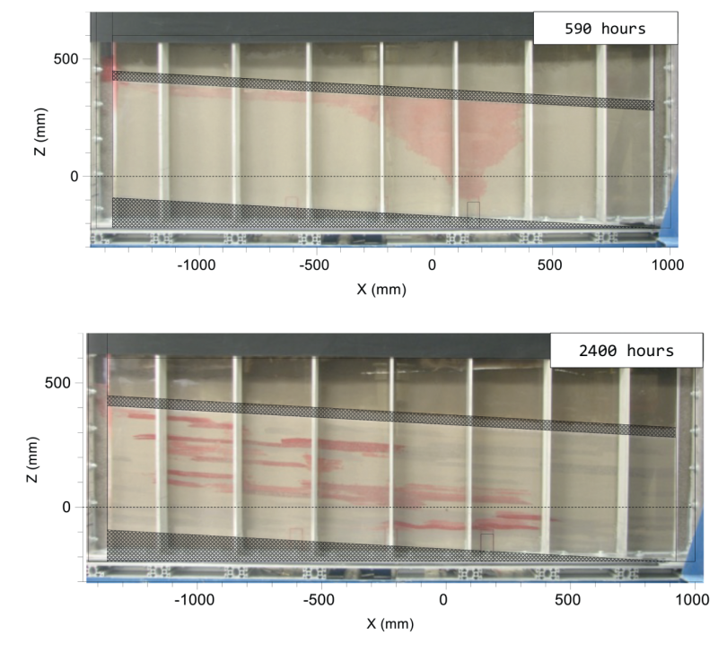
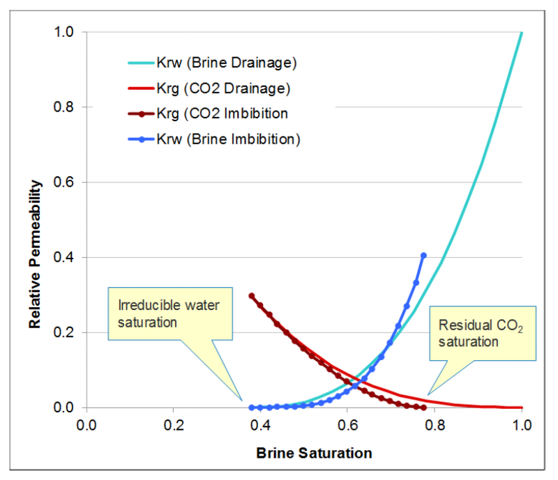
Capillary forces play a vital role in trapping CO2. Capillary trapping of injected CO2 in porous media prevents it from moving upward. The volume of residual phase of CO2 is influenced by the pore-scale network of the rock and relative permeability endpoints (demonstrated by relative-permeability curves) as shown in Fig. 4.
Solubility Trapping
CO2 dissolves in the aquifer fluid, increasing its density. Hence, the process is known as solubility trapping. However, observations from natural analogues suggest that the reaction is very slow.
Mineral Trapping
Interaction between formation rock, fluid, and CO2 can result in precipitation of carbonate minerals, such as calcite, dolomite, and siderite. This method of trapping is known as mineral trapping and is the slowest out of the four but most enduring.
Carbfix, an Icelandic consortium, have been studying the potential of CCS in basalt. They have recorded rapid mineralization of CO2 in the rock (TGS, 2024). In this process, a solution of CO2 and water is injected into basalts. The density of the CO2-water solution reduces its buoyancy (compared to gaseous phase) and forces the CO2 to the bottom of the reservoir, lessening the prerequisite for a tight caprock. This is seen as a significant improvement over sedimentary storage.
How Much CO2 Can We Store?
Depleted oil and gas fields trap CO2 both physically (structural and stratigraphical trap) and geochemically (residual trap). But to store in depleted fields, residual hydrocarbons need to be extracted to create pore space for injected CO2. Hence the recovery factor of the field will play a significant role to become a suitable GCS site.
The factors that make a reservoir suitable for high recovery are its reservoir quality (e.g. permeability), connectivity, heterogeneity, viscosity of fluid, and wettability. Developmental history such as well spacing or production mechanism can also impact recovery from a reservoir.
The right balance of storativity or storage capacity (structural/stratigraphic trapping) and storage efficiency (residual trapping) make the reservoir more favorable for GCS. For example, turbidites rank high in terms of physical trapping but poor in terms of efficiency (Hamood Al Shabibi, PDO-Heriot Watt, 2021). Whereas Aeolian dunes may provide excellent injectivity near the well, high horizontal permeability may risk the CO2 plume to move spatially over long distances (and potentially outside license boundaries).
In case of an aquifer, storage efficiency is the ratio of volume of CO2 injected to the pore volume in the rock (Bachu, 2015). Swept volume is controlled by plume dynamics, i.e., initial drainage during placement of CO2 plume, followed by reinvasion of water as the plume migrates. One of the reasons that saline aquifers rank higher than depleted hydrocarbon reservoirs for CO2 storage is that they are well dispersed with respect to expected CO2 sources. The lateral extension of saline aquifers allows huge potential volumes of CO2 to be trapped.
Can We Store CO2 Safely?
CCS projects are part of many countries’ sustainable strategies for the reduction of carbon emissions.
Depleted oil and gas reservoirs can be safe sites for GCS for multiple reasons such as the availability of extensive subsurface data and the readiness of geological and reservoir models. However, the benefit of existing infrastructure of wells and pipelines can also be viewed as a risk.
Legacy infrastructure may not be adequate for use with carbon. Further, if the storage site is a depleted oil and gas field then a caprock with the plugged wells will be comparable to a pin cushion. A thorough integrity study of the wells is needed to ensure that old wells do not become pathways for the release of stored CO2.
Another consideration is the possibility of induced seismicity. Lower-magnitude earthquakes may be triggered in some formations when enormous volumes of CO2 are injected (Zoback & Gorellick, 2012).
From this perspective, depleted reservoirs are safer because of lower reservoir pressure. When CO2 injection is initiated in the reservoir, the pore pressure would be lower than its initial value (before production started). This means that CO2 can be injected before pressures in the GCS site rise to pre-production values, thereby reducing the chance of activating earthquakes.
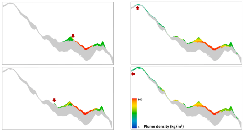
Methane leak risk is a consideration in depleted fields. A study was carried out on the impact of CO2 mixing with trapped hydrocarbons and compared with a situation when no gas was initially present (Ghanbari, et al., 2020). It was observed that methane-rich gas was displaced by CO2 plume, pushing the gas to a shallower level (Fig. 5).
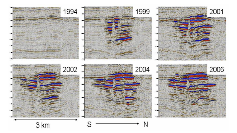
This brings us to the need of monitoring GCS sites for safe operations. Observational wells and geophysical monitoring systems, such as 4D seismic, have proven to be excellent means to observe the migration of injected CO2 in the subsurface (Fig. 6).
Can We Store CO2 Cost Effectively?
The customized nature of CCS projects makes it more complex (Mhairidh Evans, 2021). As such, the availability of project benchmarking is important.
The upcoming projects to increase storage capacity are expected to cost more as the easier ones are already in place (Mhairidh Evans, 2021). However, increased research and collaboration on CCS projects have the potential to bring down the cost.
Research to study the advantages of rapid basalt mineralization and outcomes of injecting CO2 in different phases (liquid, gas, or supercritical solutions) make finding technoeconomical storage solutions conceivable (TGS, 2024). In addition, data from existing injection wells and advancements in seismic processing and monitoring make evaluation for optimal CO2 storage sites possible.
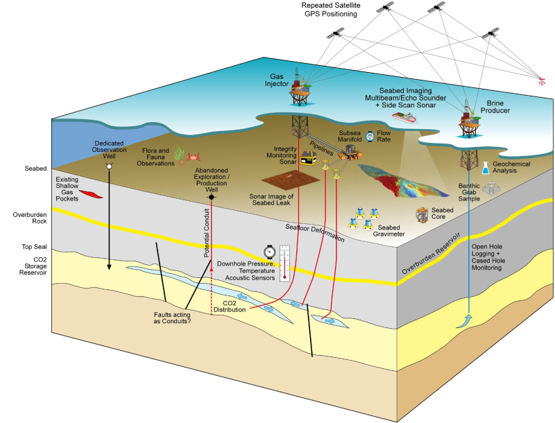
Though 4D’s contribution in GCS monitoring has been exceptional, it is an expensive technique. Other technologies as depicted in Fig. 7 are being assessed (e.g., temperature sensors in wells) to bring down the monitoring cost.
Location of storage sites (onshore or near shore) will be preferred over deepwater projects from the economic perspective (Zoback & Gorellick, 2012).
What Is the Ideal Location for Storing CO2 Underground?
A composite containment system rather than a typical petroleum seal is ideal for CO2 sequestration. Interbedded reservoirs can provide an excellent stratigraphic trap. Porous, permeable reservoir facies with extensive lateral extension can store higher volumes of CO2.
A weakly cemented pore network effectively traps CO2 by residual trapping. Highly porous reservoirs adjacent to salt domes, such as the US Gulf Coast, rank highly as preferred GCS sites because salt formations provide excellent seals for hydrocarbons (Zoback & Gorellick, 2012).
Globally, we emit more than 35 billion metric tonnes of CO2 each year. With current technology, in a year even the best GCS site can only inject a maximum of 1 million tonnes of CO2. At this rate, the challenge will be to find 3,500 more such comparable sites to significantly reduce CO2 emissions by using GCS.
For Further Reading
A Criteria-Driven Approach to the CO2 Storage Site Selection of East Mey for the Acorn Project in the North Sea by J. Alcalde, et al.
Review of CO2 Storage Efficiency in Deep Saline Aquifers by S. Bachu, Alberta Innovates—Technology Futures.
Supercritical CO2 and H2S—Brine Drainage and Imbibition Relative Permeability Relationships for Intergranular Sandstone and Carbonate Formations by D. Bennion, Hycal Energy Research Laboratories Ltd.; S. Bachu, Alberta Energy and Utilities Board.
Composite Confining Systems: Rethinking Geologic Seals for Permanent CO2 Sequestration by A. Bump, The University of Texas at Austin.
Impact of CO2 Mixing with Trapped Hydrocarbons on CO2 Storage Capacity and Security: A Case Study From the Captain Aquifer (North Sea) by S. Ghanbari, Heriot-Watt University.
Storage of CO2 in Saline Aquifers–Lessons Learned From 10 Years of Injection into the Utsira Formation in the Sleipner Area by C. Hermanrud, StatoilHydro Research Center.
Carbon Capture and Storage: How Far Can Costs Fall? by M. Evans, Wood Mackenzie.
Measurement, Monitoring, and Verification of CCS Projects with Co-Location Considerations, North Sea Transition Authority.
Why CCS is Not Like Reverse Gas Engineering by P. Ringrose, Norwegian University of Science and Technology.
How to Store CO2 Underground: Insights From Early-Mover CCS Projects by P. Ringrose.
The Geomechanics of CO2 Storage in Deep Sedimentary Formations by J. Rutqvist.
Basalts—The New Path for Permanent CO2 Storage, TGS.
CO2 Storage Screening for Contrasting Reservoir Types Based on Outcrop Analogues and Producing Reservoir Data by H. Al Shabibi.


