
The purpose of this article is to advocate the application of process design method and documentation (PDM&D) to well design and construction, what "drilling" broadly covers, and thereby align with and take advantage of the approach to design and construction used elsewhere in the oil and gas (O&G) industry.
PDM&D is widely used in engineering, procurement, and construction (EPC) firms for the design of refineries, chemical process plants, offshore topsides, storage facilities, etc. To date, it is not used in well drilling.
While well drilling and construction is different from what is done with process design in the wider oil, gas, chemical, and other industries, process design is adaptable and can be applied in many situations involving the flow of measurable things. The elements of it can be used in models of small, large, simple, or complex constructions.
Well Drilling—An Application Example
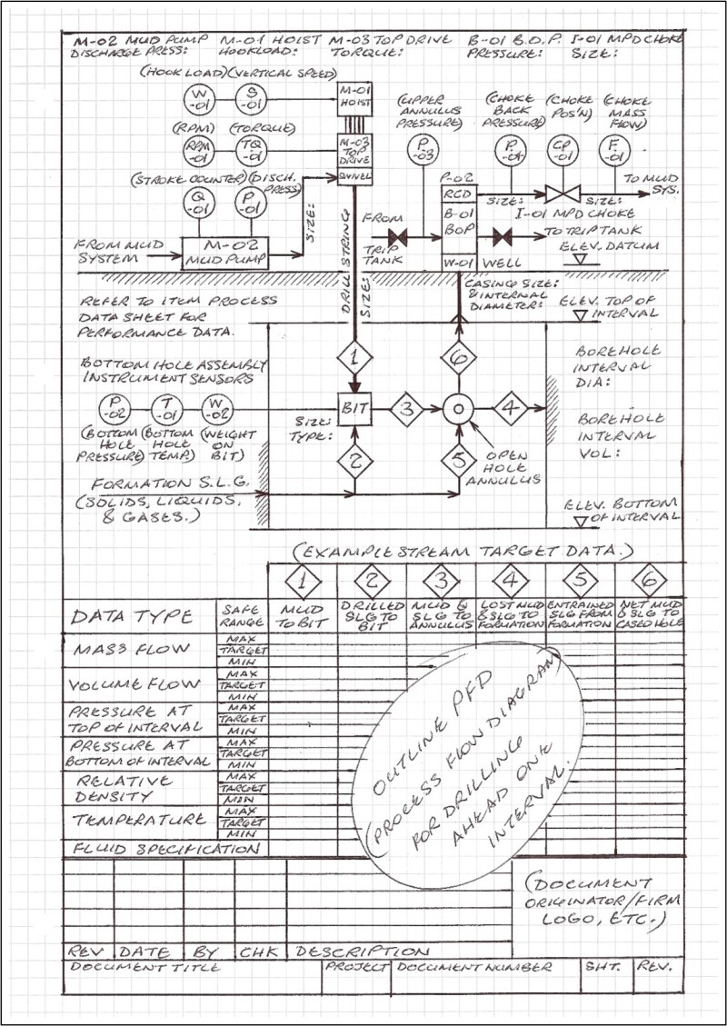
The well drill—looked at in process terms—is a "cutting and mixing machine." It cuts the rock formation, mixes the formation's solids, liquids, and gases with the drilling mud which then transports the solids, liquids, and gases to the surface. In the openhole stage, solids, liquids, gases, and drilling mud may be lost to the formation, and solids, liquids, and gases may be entrained from the formation.
The net solids, liquids, gases, and drilling mud of the openhole stage then flows into the casedhole stage and up to the surface plant. The foregoing may be shown as numbered process streams and detailed per substance identifications with operating targets and safe ranges for densities, mass flows, flow volumes, pressures, temperatures, etc.
Together with the identification of equipment and important equipment sizing, these are typical details of process flow diagrams (PFD). See Fig. 1.
The same approach may be used for running and cementing casing. Injections of drilling mud, spacer fluid, cement slurry, and any of these lost to the formation, and any ingress of formation fluids into the wellbore may all be shown as process streams and detailed in the same way used in the PFD for drilling.
PM&D in Industry
The oil and gas industry has been a host to many large complex technical projects which have been successfully executed in terms of meeting technical objectives, time, and budget constraints.
Compared to similarly sized projects in the public domain such as civil infrastructure and defense in which significant cost and time overruns and reduced deliverables are commonplace, the execution is a class apart—how is this so?
The employment of process design is at the heart of the matter. Process design might be thought of solely as a narrow discipline for dealing with complex chemical processes, but from dealing effectively with that complexity it has developed into an excellent means of dealing with complexity in much wider and different situations.
The means consists of a formal—mainly diagrammatic—documentation approach to project work in which process documents are precursors to the engineering documents.
Process documentation defines objectives, principal design schemes, and working and operating conditions and leads via engineering documentation into specifications of actual equipment and materials.
There is not necessarily an exact match between the process data and the actual equipment and materials data, since the latter must only be good enough to satisfy the process requirements. The process requirements are preserved, so for example if equipment and materials need to be replaced, the new equipment and materials should meet the process requirements—not necessarily the actual specifications of the replaced equipment and materials. This avoids a "ratcheting up" of specifications. In other words, there is no neglect of the process requirements.
The engineering documents start with piping and instrument diagrams (P&IDs) leading to mechanical data sheets, specifications, approved vendor data, layout, and detail drawings.
Engineering documentation describes actual physical equipment and materials selected to meet the requirements in the process documentation. The performance data criteria of equipment specified in the engineering documentation are based on standards, codes, regulations, and manufacturers' recommendations.
While the process documentation may specify exactly what is wanted, the engineering documentation describes what may be available. Of course, specially designed items may be closer to process requirements than off-the-shelf items.
It may be helpful to think of process data as a kitchen recipe and the engineering data as the kitchen itself. The recipe may be executed in more than one kitchen, and a kitchen may execute more than one recipe. So, while both may be closely matched, both are fundamentally different.
The objectives and principal design scheme of the work set out in the process documents and the final design described in the engineering documents are each produced and maintained in one of two separate design campaigns, with the process design campaign having primacy during the full period of the work.
The participants understand the structure and locations of data and know where to look for information. Although individual firms have their own documentation standards and procedures, the same fundamental approach is used by most, and this facilitates rapid cross-party comprehension and understanding.
Proper document identification and administration is customary because of the elaborate documentation structures, large project organizations, developing designs in an orderly fashion, and supporting the use of formal documentation instead of ad hoc documentation.
Typical PM&D Documents
Process information typically exists in block flow diagrams (BFD), PFD, and process data sheets. Engineering information exists in P&IDs, mechanical data sheets, procedures, specifications and drawings, programs, schedules, other parties’ equivalent documentation, and whatever else is required. All have their places in an elaborate documentation structure or program.
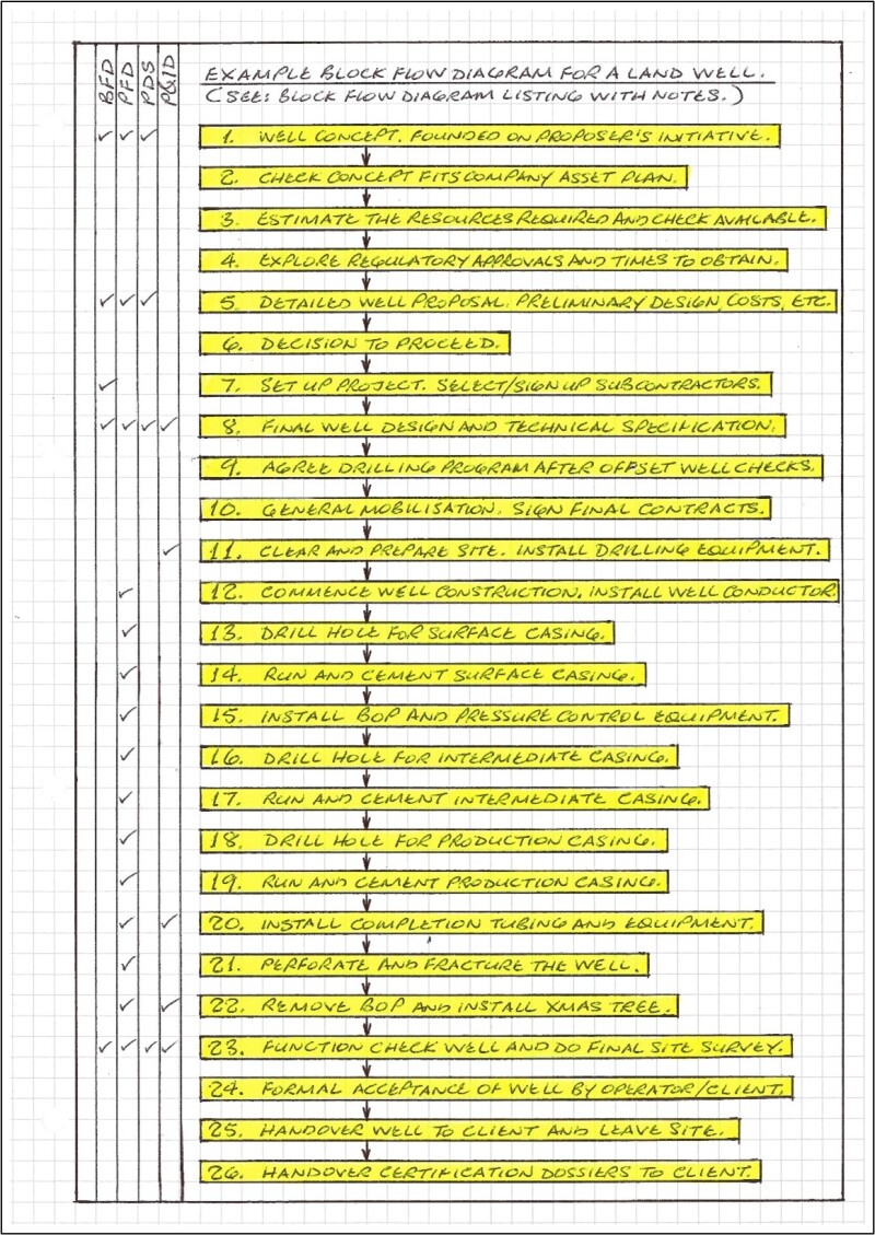
BFD shows all the main steps of the work.
Please refer to the example BFD and block flow diagram item listing with notes (Fig. 2).
PFD shows principal process/operating parameters for the step in the BFD. Also shows main equipment-sizing details and main instrument and control items. Identifies fluids but does not specify compositions of these.
Again, please refer to the example PFD which focuses on drilling a well interval.
Process Data Sheet (PDS)—each equipment item, drilling fluid, etc., has a PDS. It specifies the necessary design, material, and compositions of each item sufficient to form the basis of a mechanical data sheet for an actual piece of equipment, etc. In schedule format each PDS details the duty of the item per each relevant step in the BFD. Thus, the schedule will give the duty program for each item.
P&ID is the prime engineering document and shows the equipment and material in terms of accepted standards and codes. For example, "working pressure" on a PFD will show a particular and desired value, while on a P&ID it will be the generally accepted value in the relevant standard or code to which the equipment or material is made. P&IDs are usually very detailed with all the information necessary to the safe functioning of a system.
Current Well Drilling Culture
Why should PDM&D be applied to well design and construction (drilling)? What is to be gained? The obvious answer is commonality—the adoption of a system widely understood in O&G. Does this mean that drilling approach is not widely understood?
Drilling approach is relatively informal and lacks the obvious method of PDM&D, so it cannot be understood until it is done. Consequently, drilling approach is not widely understood by people who are not personally involved and keeping track of the work on a day-to-day basis. Rigsite work has made drilling's approach different from the approach of PDM&D done by EPC firms in head office project environments.
So, this looks like two distinct work cultures. Might it be best to leave well enough alone? Please excuse the pun.
With regard to drilling, process design is neutral and will accept any technical scheme that drilling uses or might use and without prejudice to the knowledge and experience of drilling practitioners. While PDM&D is elaborate, the use of computer programs makes it possible to manage it, PDM&D also provides the basis for a rigorous grounding for the design, approval, and use of computer programs including those used on rigsite consoles.
Block Flow Diagram Listing With Notes
1. Well Concept, Founded on Proposer’s Initiative.
Formal version of the idea founded on existing and available information and proposer's initiative. The concept incurs minimal expenditure at this stage. It may start as a discussion topic, or an existing and dormant idea. It simply requires one person or party to introduce it. It should comprise a plausible technical scheme with established or estimated reservoir details, pressure gradients, extraction performance, a cost estimate, and a plausible business case.
Includes a BFD, preliminary PFD, and PDS for any special or unusual items.
Process Documents produced: BFD, Preliminary PFD, PDS.
2. Check Concept Fits Company Asset Development Plan
If the company has an asset development plan, consider issuing a discussion version that incorporates concept.
3. Estimate the Resources Required and Check Available
What is direct cost likely to be? Management workload and other overheads? Special equipment and services?
4. Explore Regulatory Approvals and Times to Obtain
Are any official approvals, leases, and/or permits necessary and what amounts of time will be required to obtain these? Are any matters controversial? When should applications be made? Consider making a planning-type bar chart to help manage applications. Check accessibility to relevant regulations.
5. Detailed Well Proposal. Preliminary Design, Costs
Produce project outline plan and preliminary design sufficient to enable the provisional selection of major items such as the drilling rig and participants such as the drilling contractor. Cost estimates, milestones, organization, roles of participants, etc. Requires comprehensive technical details and BFD, preliminary PFD, and PDS for special or unusual items.
Process Documents produced: BFD, preliminary PFD, preliminary PDS.
6. Decision to Proceed
This might need commitments by participants provisionally selected for work. Produce report giving reasons for decision and involvements of all relevant participating parties. If the decision is not to proceed, then produce an appropriate report.
7. Set Up Project. Select/Sign Up Subcontractors
Sign up the drilling contractor. Enterprise is now "official" with core parties contractually obligated. Establish procedure for identification and administration of all technical documentation used and produced hereafter. Issue BFD. Inform all parties of project's existence, organization, contact details, etc.
8. Final Well Design and Technical Specification
Agreed with drilling contractor including choices of major equipment and material items. This means full and final design documentation: BFD, PFD, PDS, P&ID's, mechanical data sheets, layout drawings including civil site drawings, and approved vendor/equipment supplier documentation. Initiate procurement of long-lead items (this could be done earlier if necessary). This work is probably a collaboration of the operator/client, drilling contractor, and others such as mud supplier, cementing contractor, etc.
Process and directly derived documents produced: BFD, PFD, PDS, P&ID's (especially for the completed well installation), mechanical data sheets, piping and equipment layouts.
9. Agree Drilling Program After Offset Well Checks
Research by drilling contractor of any existing nearby wells and available data from public bodies and service companies. The drilling program also provides a clear contractual scope for the drilling contractor distinct from the collaboration of preceding step.
10. General Mobilization. Sign Final Contracts
Organize workforce, travel, and accommodation. Send civil contractor and site preparation equipment and materials to site.
11. Clear and Prepare Site. Install Drilling Equipment
Build access roads, well pad, mud pits, hard standing, etc. Install, check, and test all drilling and other surface equipment including utility services. Issue "ready" notice.
Documents to be used: Relevant documents produced in Step 8.
12. Commence Well Construction. Install Well Conductor
Various ways of installing a conductor: augured, drilled, piled, or a combination. Build well cellar. Position drilling rig over well bore—if conductor hole was not drilled.
Documents to be used: Relevant documents produced in Step 8, especially PFD for installing conductor. Confirm internal volume of conductor.
13. Drill Hole for Surface Casing
Install diverter spool on top of conductor and connect gravity flowline to mud pit. PFD for this step is like example PFD, but without the blowout preventer (BOP) and pressure control equipment. In this step mud density is the sole means of balancing wellbore pressure.
Documents to be used: Relevant documents produced in Step 8, especially PFD for drilling surface casing. Confirm volume of drilled hole.
14. Run and Cement Surface Casing
The PFD for running and cementing casing shows several operations in adjacent columns for: 1. Run and fill casing; 2. Attach cementing head etc.; 3. Circulate and condition mud; 4. Inject spacer liquid; 5. Release bottom plug and inject cement; 6. Release top plug and inject mud to push 5, 7. Reciprocate/rotate casing then set casing hanger; 8. Remove cement head, etc., and wait on cement. Because cement is fluid for a limited time, there is an emphasis on getting it right the first time to avoid expensive remedial work later. Cementing PFDs are detailed with items to follow and check off.
Documents to be used: Relevant documents produced in Step 8, especially PFD for running and cementing surface casing. Confirm internal volume of surface casing.
15. Install BOP and Pressure Control Equipment
This enables well to be shut in in situations where mud density alone will not balance wellbore pressure, or when the time required to circulate high- density mud is too long. The example PFD shows the BOP and managed-pressure drilling (MPD) choke.
Documents to be used: Relevant documents produced in Step 8, especially any relevant P&IDs for the surface equipment.
16. Drill Hole for Intermediate Casing
This is the first hole drilled under full pressure control regime: mud density, BOP, MPD choke, etc. The example PFD shows this. PFD will usually cover a single interval, but if significantly different conditions exist at different depths but which nevertheless allow the same casing for the entire interval, then interval may be broken into subintervals. These may be shown on one or more PFD sheets depending on document presentation rules.
Documents to be used: Relevant documents produced in Step 8, especially PFD for drilling hole for intermediate casing. Confirm volume of drilled hole.
17. Run and Cement Intermediate Casing
Because BOP is now installed, well can be pressure tested after cementing.
Documents to be used: Relevant documents produced in Step 8, especially PFD for running and cementing intermediate casing. Confirm internal volume of intermediate casing.
18. Drill Hole for Production Casing
This is the production interval and therefore the bottom hole assembly (BHA) is likely to include logging while drilling (LWD) sensors to help optimize depths of well completion elements. PFDs usually show only essential instrumentation. (All instrument and control items are shown on P&IDs, but LWD may be shown on this PFD.)
Documents to be used: Relevant documents produced in Step 8, especially PFD for drilling hole for production casing. Confirm volume of drilled hole.
19. Run and Cement Production Casing
A good cement job above and below perforation zone to contain producing strata may be required. Full-depth casing or a liner hung on the bottom of the preceding casing may be used.
Documents to be used: Relevant documents produced in Step 8, especially PFD for running and cementing production casing. Confirm internal volume of production casing.
20. Install Completion Tubing and Equipment
The production PFD applies here. Because this equipment is not temporary, a P&ID for the production setup should also be followed.
Documents to be used: Relevant documents produced in Step 8, especially production PFD and P&ID.
21. Perforate and Fracture the Well
The perforating gun containing strip-mounted shaped charges is run down the completion tubing and withdrawn after use or dropped into the bottom of the wellbore. The fracturing liquid contains sand to prop open the fractures. A PFD is required.
Documents to be used: Relevant documents produced in Step 8, especially PFD for perforating and fracturing well. The well is flow tested to confirm original estimates.
22. Remove Bop and Install Tree
Also connect to surface plant if present. This may be the final construction task and also may put well into potential production state. Production PFDs, P&IDs, data sheets, layout drawings, etc., should exist for this stage.
Documents to be used: Relevant documents produced in Step 8, especially production PFD and P&ID.
23. Function Check Well and Do Final Site Survey
Function check well installation, remove any temporary equipment fitted to and about completed well, clean site, and make preparations to leave site. Produce final site survey and as-built drawings, etc.
Documents to be used: Relevant documents produced in Step 8.
24. Formal Acceptance of Well by Operator/Client
May be in checklist format to manage any outstanding issues.
Documents to be used: Relevant documents produced in Step 8, to be used for checking constructed well installation.
25. Hand Over Well to Client and Leave Site
Site to be left in condition specified in relevant work contract(s).
26. Hand Over Certification Dossiers to Client
Certification to include equipment and material test certificates, site surveys, well logging data, etc. (Dossiers are likely to be completed off site.)
