Often when evaluating waterfloods, the focus is on issues at the well level: pumping fluid off a producer or making sure an injector doesn’t have plugged perforations. These are important issues that need to be addressed to optimize a waterflood, but focusing solely on the wells makes it easy to forget that each well is only one part of a bigger system. Losing sight of the reservoir means losing sight of other influencing factors that are affecting each well’s individual performance. Everything is connected and each change made on a single well affects all wells across the field. For this reason it is important to diagnose a waterflood from multiple viewpoints: the field, pattern, and well levels.
At the field level, the goal is to understand the reservoir as a whole. Knowing its history leads to knowing its current state and predicting how it will behave in the future. Every question is a piece to the puzzle and the more questions answered the closer you are to seeing the big picture. Examples of questions that add valuable context to the data:
- When was the field discovered?
- What was the development plan, i.e. was the acreage drilled all at once (development) or did drilling expand from a central area (exploratory)?
- Were infill wells drilled later (downspacing)?
- What does the reservoir look like?
- Are reservoir properties consistent across the field?
- What were historical well rates? Pressures?
- What type of artificial lift was used to unload wells?
- When did injection start? Was a pilot implemented?
- What were historical injection rates?
- Were injectors new drills or conversions?
For this article, I am using public data for a Permian field in New Mexico, Field EOR. The field originally started producing in the 1940’s from the Drinkard formation (a carbonate reservoir); in Texas, the Blinebry, Tubb, and Drinkard formations are referred to as the upper, middle, and lower sections of the Clearfork formation, respectively. This field is spread across four sections, approximately 2,500 acres in area.
Surveillance plots are a quick look at the field in its entirety and can provide direction for further diagnosing waterfloods. The following five plots provide a big picture view at the field level (Graphs 1–5).
- Rate vs Time Production
- Oil Rate vs Cumulative Oil
- Recovery Factor (RF) vs Injected Pore Volume (PVi)
- Voidage Replacement Ratio (VRR)
- Cumulative Fluid Produced vs Cumulative Water Injected
Graph 1: Field Production Plot, Rate vs Time
Pairing an analysis of a field production plot with a base map helps put things in better context, but even alone there is a lot of valuable information to unpack from a field production plot. The "Field EOR", shown in Graph 1 below, was discovered and started first production in the mid-1940’s. Production was on primary recovery until the late 1960’s when injection first began. During the initial 20 years of primary recovery, the oil rate fell from 4,000 BOPD to 250 BOPD. Graph 3, which we will discuss later, shows that the recovery factor was only 5% before injection. With plenty of oil remaining in the reservoir and only about ten producers shut-in during the first 20 years, we can conclude the production rate decline was an effect of energy loss in the system. This can be confirmed by the field’s gas-oil ratio (GOR) curve.
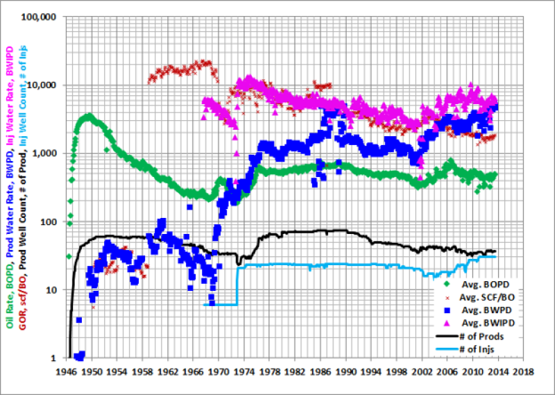
Caption: Data displayed for Field EOR. Curves plotted include oil production, water production, water injection, GOR, production well count, and injection well count.
From 1959 until injection began, the GOR steadily increased, indicating the reservoir pressure had fallen below bubble point. As gas came out of solution downhole, the produced gas volume increased and the mobility of the oil remaining in the reservoir decreased. The specific time when the reservoir pressure dropped below bubble point can be estimated by the oil rate curve. Oil rate’s biggest drop occurred in the early 1950’s. Since the number of active producers did not change at this time, the rapid drop was probably caused by a change in flow dynamics within the reservoir. If gas volumes had been reported at this time, the GOR would have rapidly increased as the oil rate dropped, a sign of gas coming out of solution.
In the late 1960s six injectors were brought on line. Ideally, a waterflood will have a 1:1 ratio between injectors and producers. When a field of 60 plus wellbores brings six injectors online, it is safe to assume this was a waterflood pilot, i.e., a proof of concept. Comparing producer and injector well count curves indicates these injectors were conversions. It is important to note which injectors are new drills vs. conversions for diagnosing injection problems later, more details on this in the well level viewpoint.
As seen during primary recovery, the GOR curve is a good gauge of whether or not the reservoir is receiving sufficient injection for pressure maintenance. A decreasing GOR curve is the first sign of successful pressure maintenance. After about 1.5 years of injection the GOR curve for Field EOR began a sharp decline. It took another 6 months to see an increase in oil rate, the first waterflood response, i.e., a sign that injected water was pushing fluids around in the reservoir. The long time delay between the start of injection and the increase in oil rate could be contributed to several factors:
1) Low quality reservoirs have impeded flow. Carbonate reservoirs are generally of lower quality (lower porosity and/or permeability) than sandstone or limestone reservoirs. The lower the permeability, the slower fluids flow through the reservoir and the longer it takes to see a waterflood response. Rule of thumb: it is preferable to waterflood reservoirs with a permeability greater than 3 mD. Fields with lower permeabilities can be flooded, but the cycle time will be much longer.
2) Well spacing is too wide. It takes more time for fluid to flow between injectors and producers that are spaced farther apart. Carbonate Permian fields typically have 20 acre or tighter well spacing. Clean sandstone fields can flood effectively at much wider spacing; I have observed successful waterfloods at 80 acre well spacing in Egypt.
3) Large reservoir voidage. Production has significantly depleted the reservoir and reduced the energy in the system. Large volumes of water will need to be injected to replace the produced volume and increase reservoir pressure. Reservoir voidage can be calculated by converting cumulative production volumes (remember to convert produced gas into a liquid volume equivalent) at surface to reservoir volumes using formation volume factors (FVFs). The VRR plot, Graph 4, is used to visualize reservoir voidage and identify reservoir fill-up.
After a 5 year pilot study, the waterflood was expanded across Field EOR. The overall well count did not exceed the number of available wellbores, so it can be assumed most of the new injectors were conversions. As the field started to see an increase in oil rate from waterflooding, the operator began an infill drilling program. Towards the end of the 1970s, 30–40 new producers had been drilled. Throughout the infill drilling program, the GOR curve was erratic but continued its downward trend indicating the field was receiving sufficient injection support. The oil rate increased as new producers came on line and continued to increase through the 1980s in response to the waterflood.
No additional activity was apparent until the 2000s when the operator began infilling with horizontal producers. Injection ramped up at the same time the horizontal wells were brought on line. With no change in the injector well count, the increased injection rate was made possible by a workover program, i.e., injector cleanouts and/or reperforations to reduce injection pressure and increase injection rates. As the horizontal wells began to steeply decline in the late 2000s, focus switched to improving injection support by converting shut-in producers to injection. The overall injection rate did not increase with the additional injectors. When new injectors come on line it is expected that the overall injection rate for the field will increase. Since this did not happen, the field has either a water source problem or surface restraints that need to be addressed prior to future development.
Taking the time to analyze the field production plot gives a great deal of insight into how the field was developed and the state of the reservoir. Important takeaways include:
- Primary drive is pressure depletion with no aquifer present. An active aquifer would have helped maintain reservoir pressure and there would have been more water production prior to injection.
- Reservoir pressure fell below bubble point in early 1950s. The oil is going to be less mobile since a large volume of gas has come out of solution. It will require more water cycling to sweep the oil, expect to see fingering effects.
- Most/all injectors were converted from existing producers. There could be significant wellbore integrity issues and/or conformance issues that are decreasing the waterflood’s efficiency.
- Fill-up time was approximately 2 years for waterflood pilot. In this reservoir, it will take longer to replace the voidage in a depleted area. Waterflood responses will be delayed if fill-up is not maintained.
- Proven waterflood success in pilot and expansion. Multiple examples of positive responses to injection. GOR decreased indicating pressure maintenance is possible. Oil rate increased indicating waterflooding is possible.
- Multiple rounds of infill drilling with max well count of ~110 active wells. This field spans across ~2,500 acres and was downspaced to roughly 20 acre well spacing with vertical wells. In areas where horizontals were drilled, it is closer to 10 acre well spacing.
- Water source and/or water handling surface restrictions. The field’s maximum injection rate is 10,000 BWIPD. If more injection is needed for future development plans, water source and/or water handling facilities will require additional investment.
- Successful cleanouts can increase injection rates. Workovers performed on injectors more than doubled injection rates.
- Field Timeline.

There is less to unpack in each of the remaining surveillance plots; each plot focuses on a single aspect of the reservoir or main takeaway. Below, Graph 2 shows the field’s oil rate plotted against cumulative oil production. Plotting rate on a cumulative scale reduces shut-in noise and makes trends easier to identify. Extrapolating lines through these trends gives a rough forecast of field reserves. The forecast is “rough” because it assumes no change in field conditions going forward. This plot can be used to determine an estimated ultimate recovery (EUR) for each phase of development through the field’s history. It can also help determine the secondary to primary ratio (S/P ratio) for easy analog comparison.
Formula 1: Secondary to Primary Ratio (S/P Ratio)

Use S/P ratios from analog waterfloods to calculate a reasonable target recovery for your field.
Calculating the S/P ratio for the field is a matter of plug-and-chug using Formula 1. Determine the secondary EUR by subtracting the primary EUR from the total EUR. Then divide the secondary EUR by the primary EUR to get the S/P ratio. In this example, the secondary EUR is a combination of waterflood recovery and multiple infill drilling programs. Since there is some amount of primary recovery for each new drill included in the secondary EUR, Field EOR should have a higher S/P ratio than its analogs.
Graph 2: Field Oil Rate vs. Cumulative Oil Production
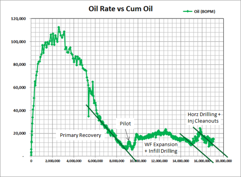
Caption: Data displayed for Field EOR. The three trend lines drawn represent rough EURs for different phases of development, e.g., primary recovery, waterflood pilot, secondary plus infill recovery, and secondary plus horizontal infill recovery.
The first trendline forecasts the field EUR under primary recovery at 9.4 million bbl of oil. The last trendline forecasts the total field EUR at 18.4 million bbl of oil. Plugging these numbers into Formula 1, returns a 0.96 S/P ratio for Field EOR. It is generally expected that the S/P ratio will be greater than 1.0 for a carbonate Permian field under waterflood. With a calculated S/P ratio below 1.0, there is potential upside with waterflood optimization or additional downspacing to improve the performance of this field.
While S/P ratio is an effective tool for comparing waterfloods, recovery factor (RF) is more commonly used. Graph 3 plots RF against cumulative water injected as a percentage of the reservoir’s pore volume. Conventional Permian fields have on average a total RF of 25% with 7–15% being contributed to primary recovery and the remainder to enhanced oil recovery. Depending on how clean the rock is, reducing oil saturation down to residual oil could take anywhere from 0.75 to 5 or more pore volumes of injected water. With that in mind, Graph 3 confirms that Field EOR has a large amount of upside; if it is average for the area, it has to recover 1.5 times its current cumulative production.
Graph 3 - RF vs. Injected Pore Volume (PVi)
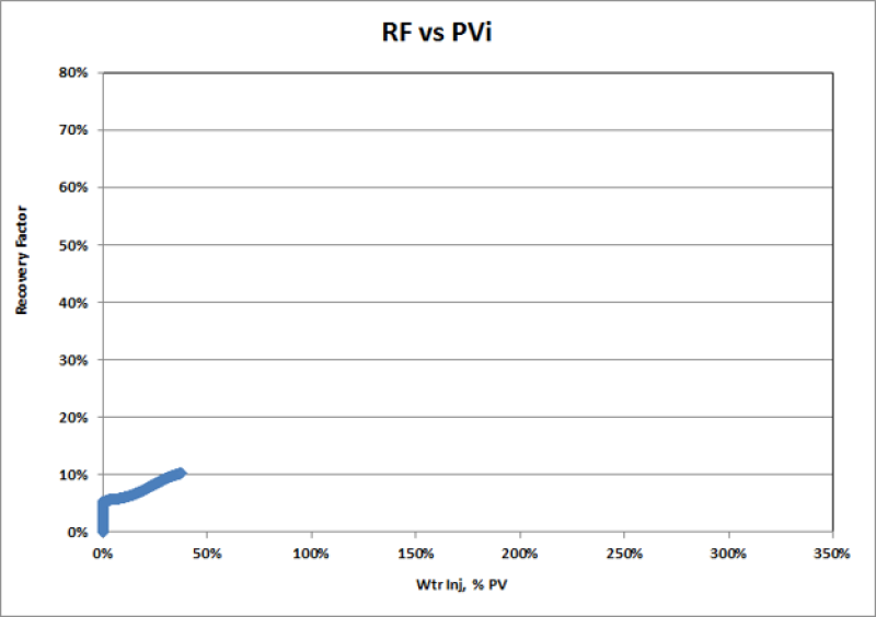
Caption: Data displayed for Field EOR. Use caution when comparing with published RF for other fields. Original oil in place (OOIP) could be calculated differently (net vs gross) which would cause large variations in RF.
When improving waterflood performance the first thing to confirm is that the field is actually under waterflood. Fields that have been injecting for years could still be in the pressure maintenance phase if fill-up was never achieved. The voidage replacement ratio (VRR) plot, Graph 4, is ideal for identifying when fill-up is reached and monitoring the field’s voidage. The VRR is the injected volume divided by the produced volume (Formula 2). Fill-up is reached when the cumulative VRR equals 1.0; after achieving fill-up many operators set a target VRR of 1.2 to maintain fill-up. Most set a target above 1.0 because it is assumed that some injection will be lost out of zone.
Formula 2: Voidage Replacement Ratio (VRR)
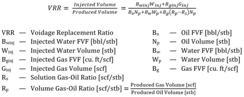
Use this formula to calculate cumulative or instantaneous VRR and plot on Graph 4.
Graph 4: Field VRR Plot
Caption: Data displayed for Field EOR. Curves plotted include instantaneous and cumulative VRRs. Instantaneous VRR curve is calculated on a monthly basis.
In Field EOR, the waterflood pilot injected at extremely high rates in an attempt to quickly reach fill-up and see results. The high initial rates means instantaneous VRR starts high but drops as the waterflood expands and the initial infill drilling program begins. Referring back to Graph 1, as the field is downspaced and injection ramps up there is an increase in water production (water breakthrough), signs of a fast zone, or fingering effects. As the total production volume approaches the injected water volume, the instantaneous VRR begins to fall. The cumulative VRR will always trend in the direction of the instantaneous VRR. As the monthly VRR drops, the cumulative VRR will decline as well. There is a caveat to using this plot, it is calculated based on the volumes measured at the surface. What is injected at the surface is not guaranteed to make it to the target zone.
How do we know if the volumes injected at the surface make it to the reservoir? Determine the reservoir’s material balance. Is the reservoir a closed system? Is an active aquifer helping with pressure maintenance? Is a passive aquifer stealing injection water? After achieving fill-up, Graph 5 can be used to determine if the reservoir is a closed system, i.e., the injected volume results in an equivalent produced volume. The cumulative fluid curve will plot in a straight line around a 45º angle in a closed system. If more volume is produced than injected, the curve bends upwards indicating there is an influx of fluid. This most often happens when a strong aquifer is present. If less volume is produced than injected, the curve will plateau indicating fluid is leaking off. This most often occurs in the presence of a thief zone, e.g., non-conformance, wellbore integrity failure, and passive aquifer.
Graph 5: Cumulative Fluid Produced vs. Cumulative Water Injected
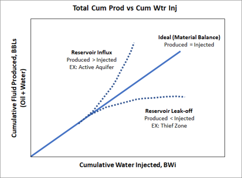
After achieving fill-up, this plot is a quick look at the reservoir’s material balance, i.e. if the reservoir is a closed system (IN=OUT), if fluid is leaving the reservoir (Leak-Off), or if fluid is entering the reservoir (Influx).
Reviewing these five surveillance plots provides clarity and direction for the rest of the waterflood diagnosis. For example, Graph 1 implies all the injectors appear to be conversions. When completing the well level analysis, it will be prudent to look for signs of wellbore integrity/isolation issues; injection profiles are a good approach. Stepping back to look at the field level means that development methods may stand out over individual well performance. Graph 2 indicates the field is underperforming when compared to peers. The boost in EUR from infilling with horizontals suggests downspacing may improve waterflood efficiency. Downspacing could be developed across the rest of the field assuming the economics are good. The waterflood diagnosis is not over, the field surveillance plots are just the first step in understanding the problem. In the future, I plan to write additional articles on pattern balancing at the field level and/or conformance at the pattern level.
[The article was originally published in the author's LinkedIn page.]

Vanessa Glass Neal is a reservoir engineering consultant at Sethlans Energy. In her previous role, she evaluated international and domestic waterflood assets at Apache Corp. Neal has more than 14 years of hands-on experience in the oil and gas industry, with a has focus on conventional play (re)development with additional skills in managing unconventional assets, production operations, simulating reservoirs, acquisition/divestiture valuations, and mentoring young engineers. She holds a BS in petroleum engineering from Texas A&M University and an MBA from the University of Houston.

