
Drilling an oil well is a destructive process of cutting a rock formation, either by chipping or crushing. This process is often associated with shocks and vibrations at the bottomhole assembly (BHA). Modern BHAs contain sophisticated steerable systems and logging tools that are prone to failure under severe downhole conditions. Over the past few decades, engineers working in the oil and gas industry have made a continual effort to enhance tool reliability and optimize the drilling process, resulting in significant improvements in operational efficiency.
Understanding shocks and vibrations is crucial for tool design, well planning, and drilling execution. Given the implications that damaged or inoperable equipment have for nonproductive time, knowledge of the factors that affect tool reliability is important for oilfield services personnel, from project managers to field operators.
This article provides an overview of common damage caused by vibrations, the most prominent vibration modes, mitigation methods, and design principles used to diminish vibration effects.
Introduction
The rotary drilling method is the most common for oil well drilling, as it provides a high rate of penetration (ROP) and allows operators to drill deep wells through hard formations. In this system, the drilling bit is at the bottom of a drillstring, followed by drill collars and drillpipes. The drillstring is rotated by the rig (Kelly or topdrive), typically at 50 to 200 rev/min, allowing the bit to cut the formation. Drilling fluid is circulated through the drillpipe and the bit to remove cuttings out of the wellbore.
Today’s BHAs usually have a steerable motor or a rotary steerable system (RSS) above the bit that allows for drilling the well in a specific direction. A measurement-while-drilling (MWD) tool sends real-time data to the surface to control the well trajectory. Logging-while-drilling (LWD) tools are also often a part of the BHA, to allow real-time decision-making based on the measured formation properties.
All these advanced tools have sensitive components that can be damaged by the drilling environment. As the drillstring rotates, the interaction between the bit, formation, downhole fluid, and the BHA result in a very complex motion pattern that may induce different vibrational modes, as follows.
Downhole Vibrational Modes
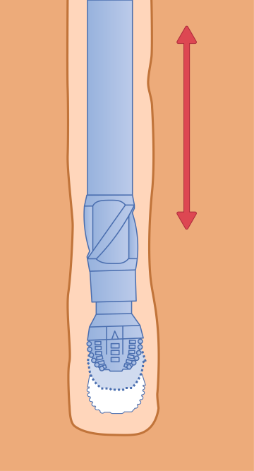
Downhole vibrations are typically classified by the direction of the motion: axial, lateral, and torsional. Axial vibration (often referred to as bit bounce) is the motion of the BHA along its axis (Fig. 1). This vibrational mode is considered less aggressive than the other modes, because the accelerations are usually low, due to the large masses that must be set in motion.
Axial vibrations are typically observed at shallow depths. The drillstring mass increases with the well depth, and axial vibrations are usually not a concern at depths of about 1,500 ft. Axial oscillations can be identified using surface weight-on-bit (WOB) indicators and can usually be mitigated by adjusting drilling parameters.
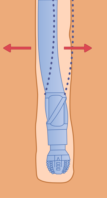
Lateral vibrations are seen as side-to-side motion in a transverse direction relative to the drillstring (Fig. 2). This transverse vibration is associated with whirl and bending of the drillstring. This can be a very destructive mode, entailing severe damage to the BHA components and wellbore, as the bit and the BHA continuously impact the borehole walls. The interaction between the BHA and the borehole wall leads to problems such as an over-gauge hole, damaged equipment, loss of directional control, and drillstring fatigue.
Lateral vibrations do not propagate well through the drillstring and often cannot be detected by observing surface parameters. Today, most “smart” downhole tools contain shock sensors that measure lateral acceleration to identify transverse vibrations in real time, to take corrective actions before severe damage occurs.
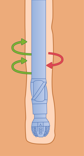
The length of the drillstring is much greater than its diameter, resulting in high flexibility. As the drillstring rotates, the elasticity, the moment of inertia, and the friction against the formation result in low-frequency (below 1 Hz) twisting motion along the drillstring (Fig. 3).
Although the speed is constant on the surface, the rotation along the drillstring can be irregular. This speed variation is called torsional oscillation, or stick/slip. Torsional oscillations are more pronounced with small-diameter drillpipe and in highly inclined wells. Stick/slip causes the drillstring to periodically get torqued up, and then spin faster than the surface rotation. This motion may result in over-torqued pipe connections and damaged bit cutters. Severe forms of stick/slip can fatigue the drillpipe, resulting in a washout or a twistoff. High angular accelerations and irregular torque cause solder joint fatigue on circuit boards. Joints in bulky components such as inductors, transistors, and big capacitors are especially susceptible. Stick/slip can be identified on the surface by observing the torque oscillations. Modern BHAs also have tools capable of measuring downhole rotation speed and its variation.
The interaction of the bit with the formation can also cause another torsional vibration mode often referred to as high-frequency torsional oscillations (HFTOs). HFTOs can be observed when a hard formation is drilled with an aggressive bit. As the vibrations originate at the bottom, they are disastrous to the bit and adjacent drilling, telemetry, and logging tools. Due to the frequency of 20 to 200 Hz, this vibration may not be identified with angular position sensors, which are used for the rev/min measurement. The BHA requires an off-axis mounted accelerometer package or a torque-sensing load cell to identify HFTOs. Such sensor packages are not available in all tools but are becoming more common as the industry recognizes their value.
Severe shocks and vibrations have always had a major negative impact on reliability, often resulting in damage to the drilling bit, collars, stabilizers, connections, and downhole tools. Before the advent of MWD and LWD tools, the BHA could often tolerate severe downhole conditions. However, modern high-tech tools are more susceptible to damaging downhole environments than conventional equipment.
Common Tool Failure Modes
As drilling technology advances, the integration of electronic components into downhole tools has revolutionized the oil drilling industry. Modern BHAs now incorporate intricate electronic and mechanical systems, including telemetry, RSS, and LWD tools. However, this technological progress comes with its own set of challenges, particularly regarding the susceptibility of these complex tools to damage from shocks and vibrations.
Advanced downhole tools are built into special drill collars, which are part of the BHA, and are exposed to downhole pressure, temperature, shocks, and vibrations. Electronic boards and sensors within the tools are integral to their operation, performing crucial functions such as data collection, transmission, and control of well trajectory. These boards are typically reinforced with a metal frame and mounted to a chassis that provides more rigidity to withstand the downhole environment. Connection between multiple boards is established with wiring harnesses that run through the wire channels in the chassis. All the electronics are sealed in a pressure housing that bears the downhole pressure.
As the chassis and pressure housings are mounted to the drill collar, the relentless pounding and jarring forces exerted on the BHA can lead to a range of issues affecting the electronics. Vibrations cause solder joint fatigue over time, eventually resulting in a loss of electrical continuity. In severe cases, the component can even detach from the printed circuit board (PCB) (Fig. 4). Solder joint cracks are typically observed under large components such as field programmable gate arrays, microcontrollers, and power transistors. If the solder joint does not fail, the PCB trace may detach.

Even if the component is not misaligned or detached, cracks of the PCB traces in the solder joints compromise the function of the board. Intermittent electrical contact may cause various issues, depending on the board, the component, and the tool function. In the worst case, a loss of a single component may take down the entire BHA. For example, if the MWD power supply stops functioning, there will be no telemetry. Without real-time telemetry, there is no use for the other tools, and such failure will result in pulling out of hole.
High shocks can also crack the board mounting frames. Without proper support, the vibrational motion increases, resulting in component damages as discussed above, as well as internal PCB damages.
Intensive vibrations cause micromotion between various parts of the tool. The friction between the harness wires and the chassis eventually results in insulation wear. Insulation failure will result in a short circuit, and the tool may lose some or all of its functions. A short circuit of a high-power line can cause excessive heat generation and a fire that can burn the costly electronics. Electrical connectors are also susceptible to vibrations and will eventually fail.
The micromotion of solid connectors relative to the harnesses causes the wires to flex. In this situation, the cyclic load is highest at the joint between the wire and the connector. Eventually, this leads to a wire failure. Similar to component issues, a continuity failure may compromise the whole BHA.
Besides affecting the electronic components, shocks and vibrations also compromise the mechanical integrity of downhole tools. As previously mentioned, the tool electronics are protected from the high-pressure environment by a pressure housing. The pressure seal is achieved by using rubber O-rings. Vibrations cause friction between the O-rings and the sealing surfaces, which may result in severe O-ring wear, especially at high pressures and temperatures. This wear will compromise the seal, causing the tool to be flooded with the drilling fluid.
Micromotion also causes friction and fretting between internal mechanical components. The chassis is usually built of several sections, with joints between the sections. Some clearance must be allowed between the joints so that one part can fit into another. Vibrations can make the two parts rattle against each other, resulting in fretting damage. Since the chassis walls are too thin for welding repair, expensive parts must often be scrapped.
Fretting also occurs between smaller mechanical parts such as gears, shafts, and other transmission components, causing damage (Fig. 5).
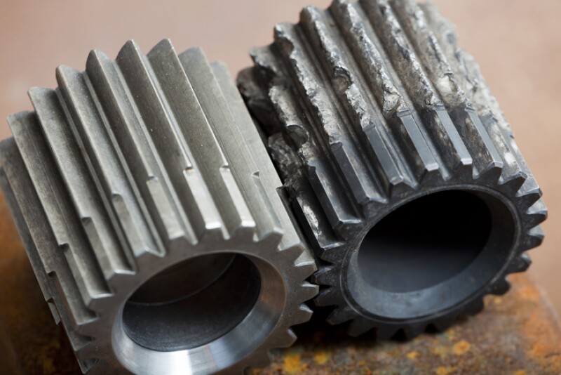
In addition to wear and mechanical damage, fretting also generates metallic dust that accumulates inside the tool. The dust is electrically conductive and can thus affect the electronic boards. In the worst-case scenario, an electrical short circuit will cause a catastrophic failure.
Telemetry and steering tools have a complex mechanical design featuring thousands of small parts.
Many of these parts are made of hard materials to minimize wear and erosion. However, hard materials are often brittle and crack under high shocks.
In general, high-tech tools are more prone to failure than conventional drilling equipment. To be economically feasible, modern tools must survive the drilling process without suffering serious damage. The oil and gas industry continues to take measures to enable reliable, safe, and efficient drilling.
Solutions To Improve Drilling Tool Reliability
Downhole drilling tool failure occurs in two typical modes. On the one hand, when the vibration frequency is close to the natural frequency of the drillstring, drillstring resonance occurs, and the peak response value approximates or exceeds the limit strength of drilling tools breakage failure. On the other hand, drilling tools show fatigue damage in an environment with long-term or repeated vibrations or impacts.
One of the most cost-effective methods to combat the problem of drillstring resonance is BHA design optimization. Extensive research has been conducted over the past decades, and modern computer hardware allows engineers to run complex simulations of drillstring behavior. Leading oilfield service companies can provide solutions to determine the best BHA, bit, and cutter design, as well as WOB and rev/min ratios, to maximize ROP and minimize vibrations.
The main purpose of the BHA design is to avoid resonances. This goal is commonly achieved with optimal placement of stabilizers, shock subs, and flex sections. The input of the vibrational energy into the BHA can be minimized with an appropriate selection of the bit and drilling parameters.
However, it is not possible to entirely design out shocks and vibrations. BHA design is highly restricted by the directional drilling requirements. Stabilizer location plays a crucial role in the BHA directional tendency. Even the most advanced steering tools require the natural BHA tendency to be within certain limits, requiring specific stabilizer locations, which are not always optimal from the shock and vibration standpoint. Another restriction is caused by the limited equipment selection. Downhole tools have a fixed length, and stabilizer availability is limited. There is also a high uncertainty in drillstring vibration modeling and analysis, as the actual friction factors, well trajectory, and drilling fluid properties always have some deviation from the plan.
With an optimal BHA design, it is possible to limit the vibrational energy accumulation due to resonance, but this only solves one aspect of the problem. High shocks and vibrations may occur even if the system does not accumulate energy. Therefore, downhole tools must tolerate the downhole environment.
Electronic circuit boards and sensors are highly sensitive tool parts. Similar to the BHA, vibrational analysis is done for electronic boards, chassis, and collars, to avoid vibrational energy accumulation within the tool. Verification and validation tests are performed to confirm the simulation results.
To minimize the impact of vibrations on electronics, high-grade components are utilized, and shock-resistant options are selected whenever available. Special component mounting and harness retention techniques are used to improve the vibration tolerance, cushion shocks, and prevent any motion that could damage wire insulation.
The mechanical design has also evolved to enhance durability in severe drilling environments, preventing cracking, fretting and excessive wear. The upgrades increase the tool cost, but are justified by allowing the tools to operate in harsh environments, preventing nonproductive time and increasing operational efficiency.
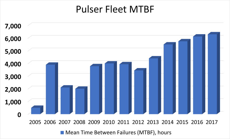
As a whole, these ruggedization measures have greatly improved tool resilience to shocks and vibrations over the past decades. For example, according to published data from an MWD and LWD tool manufacturer, the pulser fleet shows a steady increase of mean time between failures (Fig. 6), and most industry-leading companies demonstrate similar trends.
However, no tool can be made indestructible, and managing shocks and vibrations is one of the main tasks in oil well drilling. Modern tools are equipped with sensor packages that allow for monitoring downhole conditions and taking corrective actions based on real-time data. Vibrations can be mitigated by adjusting the drilling parameters such as weight on bit, drillstring rotation speed (surface rev/min, and flow rate. The effects of these adjustments vary. In the best case, these adjustments result in a smooth drilling environment and even improve the ROP. In the worst case, successful shock mitigation is achieved outside of the optimum drilling window where the ROP decrease becomes unacceptable.
When adjusting the drilling parameters fails to resolve the problem, improving the drilling fluid lubricity may help. This comes at a cost, but it is justified when compared with the larger losses due to equipment damage and time for tripping out of hole.
Conclusion
Downhole BHA motion is a complex phenomenon characterized by several vibrational modes coupled to each other. Vibration is constantly present in the drilling environment, and if not controlled, it can cause severe equipment damage and a catastrophic drillstring failure. Advanced MWD, LWD, and RSS tools are essential for efficient drilling, but their delicate electronic and mechanical components suffer in harsh downhole environments.
Oilfield service companies now realize that understanding mitigating shocks and vibration is a way to improve reliability and allow wells to continue to be drilled as planned. Modern drilling tools are designed to have a reasonable lifespan under severe conditions. Extensive research has been done on BHA dynamics, which allows us to model the behavior and optimize the BHA in the planning stage. Downhole vibration sensors along with real-time telemetry facilitate problem identification and timely intervention.
There is no single practice or tool that can eradicate vibrations. Controlling vibration is a multipronged approach that includes downhole tool ruggedization, BHA optimization, real-time data monitoring, and safe drilling practices. Practicing these methodologies in aggregate is the best method for improving efficiency and reliability in drilling.
For Further Reading
Rock Fracture and Blasting Theory and Applications by Z. Zhang.
An Introduction to Petroleum Drilling Methods by Y. Ramsaran, et. al.
Drillstring Vibration Analysis Considering an Axial-Torsional-Lateral Nonsmooth Model by L. De Moraes, CEFET/RJ; M. Savi, Universidade Federal do Rio de Janeiro.
Analysis of Whirl Characteristics of Drillstring Under Multidirectional Coupling Conditions by J. Tian, Southwest Petroleum University; et. al.
A Review of the Evaluation, Control, and Application Technologies for Drillstring Vibrations and Shocks in Oil and Gas Well by G. Dong, Southwest Petroleum University.
Drillstring Horizontal Dynamics With Uncertainty on the Frictional Force by T. Ritto, Federal University of Rio de Janeiro.
MWD Vibration Measurements: A Time for Standardization by S. Osnes, StatoilHydro ASA.
Integrated PoF and CBM Strategies for Improving Electronics Reliability Performance of Downhole MWD and LWD Tools by S. Zhan, Baker Hughes.
Study on Vibration of Directional Drillstring With Affecting the Important Parameters With Energy Considering by F. Taheran, Sharif University of Technology.
Analysis of Multi-Mode Nonlinear Coupled Axial-Transverse Drillstring Vibration in Vibration-Assisted Rotary Drilling by A. Ghasemloonia, Memorial University of Newfoundland.
Comprehensive Review of High Frequency Torsional Oscillations (HFTOs) While Drilling by Y. Zhang, University of Texas at Austin.
The MWD Revolution by A. Pickett. Permian Basin Oil and Gas Magazine.
Logging While Drilling (LWD) in Oil and Gas Industry by R. Prasad.
MWD Failure Rates Due to Drilling Dynamics by H. Reckmann, Baker Hughes.
Failure Analysis of Drillstrings by K. Macdonald, University of Stavanger.
i-DRILL, SLB
Enhance Drilling Performance Through Planning and Analysis, Halliburton.
JewelSuite Drilling Engineering, Baker Hughes
Whirling Dynamics of a Drillstring with Fluid–Structure Interaction by L. Volphi, University of Stavanger. Geoenergy Science and Engineering
Innovative Advances in MWD by C. Martin, Anadrill.
SureShot-MP, APS Technology.
