

More about this topic can be found in Gidley, J.L., Holditch, S.A., Nierode, D.A., and Veatch, R.W. 1990. Recent Advances in Hydraulic Fracturing. Monograph Series, SPE, Richardson, Texas 12.
Reasons for Hydraulic Fracturing
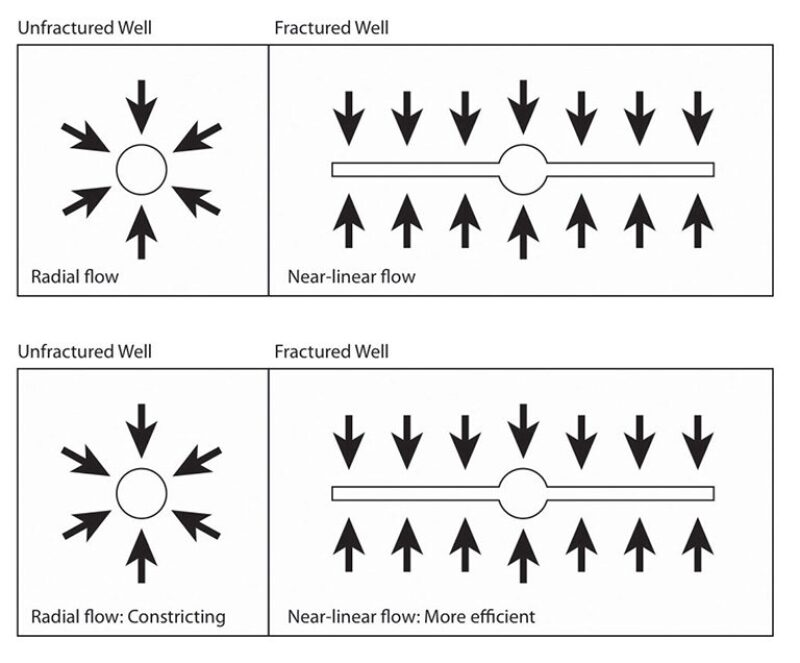
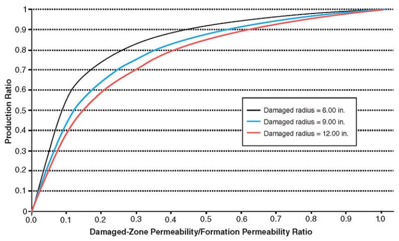
In their natural state, most oil and gas wells do not produce at their optimum level, but hydraulic fracturing can address multiple challenges to efficient production. Radial flow from the reservoir into the wellbore is not an efficient flow regime. As the fluid approaches the wellbore, it has to pass through successively smaller and smaller areas. This causes “jamming” of the fluid and reduction in flow. If one were to complete the well such that the radial flow changes to nearly linear, then the change in flow pattern will increase well productivity. A properly designed and executed hydraulic fracture can change flow from radial to nearly linear (Fig. 1). Near-wellbore permeability in most formations is reduced by drilling, cementing, and completion operations. Theoretically, one can show that this permeability reduction causes substantial reductions in production rates (Fig. 2). Hydraulic fracturing can extend the reach of the wellbore beyond the damaged area and abate its negative effect on production. Hydraulic fracturing extends the reach of the wellbore far into the formation. Production is therefore controlled by the properties of the average reservoir reached by the fracture, instead of the much smaller near-wellbore region. The net effect is a reduction in the risk of drilling into less- or nonproductive zones.
In formations with potential sand production, hydraulic fracturing enables financially viable production rates at higher bottomhole flowing pressures. This reduces the difference between far-field and near-wellbore reservoir pressures, and the tendency for sand production. Production rates from most wells eventually decline to a level below which production is not economically advisable. Hydraulic fracturing increases the ultimate recovery factor that corresponds to the economic cutoff of production. For these and other reasons, hydraulic fracturing is one of the most common completion operations in oil and gas reservoirs. Theoretically, all wells can benefit from hydraulic fracturing. However, the practice is much more common in medium- and low-permeability formations. In fact, in many low-permeability reservoirs, wells are fractured before production is even attempted and is required to exploit these resources economically.
Why and How Fracturing Helps Production
The ability of a fracture to change the flow regime and the distance the fracture reaches into the reservoir determine the production increase. Referring to Fig. 1, if the reservoir fluid is to flow into a fracture, the pressure inside the fracture has to be close to the wellbore pressure. This means that the hydraulic fracture itself should offer very little resistance to flow; in other words, it should have very high permeability. In reservoir engineering, this is measured by the term “nondimensional conductivity,” which is defined by:
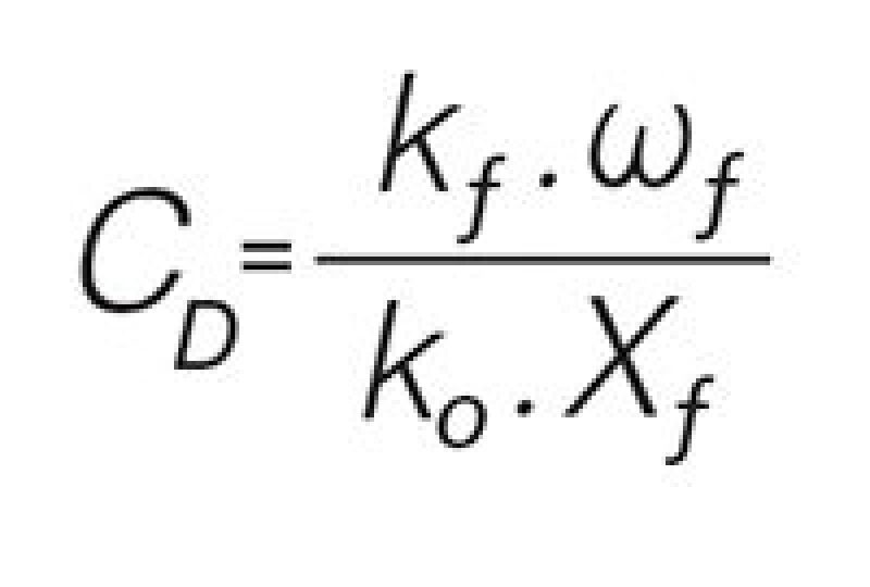
where,
CD is the nondimensional fracture conductivity
ko is the formation permeability
kƒ is the fracture permeability
ƒ is the propped fracture width
Xƒ is the propped fracture length measured from the wellbore to the fracture tip
A reasonable range for nondimensional conductivity is 1< CD<10. For example, assuming ko=1 md, ƒ=0.25 in., Xƒ=500 ft, and CD=5, it is possible to compute a required fracture permeability kƒ =120 darcies.
Thus, a highly permeable fracture needs to be created for a successful treatment. This is not to say that a less-permeable fracture will be ineffective, but rather that a substantial production increase requires a very permeable fracture. As formation permeability increases, the fracture permeability required to achieve a significant production improvement becomes very large. On the other hand, in high-permeability reservoirs, the financial returns from even a modest production increase can be quite substantial. For example, a 10% increase in a well producing 1,000 BOPD means a 100 BOPD increase, while a well producing 10 BOPD requires a much larger percentage increase in production to become financially viable. Thus, financial and technical successes in hydraulic fracturing need to be reviewed separately on the basis of different criteria.
At present, use of hydraulic fracturing is much more prevalent in low- and ultralow-permeability reservoirs. In fact, most of these reservoirs would not even be under consideration for development, were it not for fracturing (e.g., the Bakken, Marcellus, Haynesville, Eagle Ford, and many other sandstones and shales). This is particularly true in unconventional reservoirs, where horizontal drilling and the creation of multiple hydraulic fractures along the length of these wells have been enabling techniques for the development of resource plays.
Mechanics of Hydraulic Fracturing
Fluid injection at high pressures and rates causes initiation and extension of hydraulic fractures. The pressure required for fracture initiation depends on the values of the three in-situ principal stresses, formation mechanical properties, and the formation’s tensile strength. The pressure required for fracture extension is dominantly controlled by the least in-situ principal stress. Fracture orientation is perpendicular to the direction of the same principal stress.
During fluid injection, the fluid pressure inside the fracture is higher than the least in-situ principal stress, and this keeps the fracture open. But after the injection stops and pressure is allowed to drop, the fracture begins to close. To keep the fracture open and conductive (permeable) after the treatment, a proppant is mixed with the fluid and injected inside the fracture to keep it open during production operations.
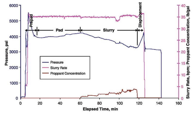
Fig. 3 shows a fracturing chart with various stages of the treatment marked on it. The vast majority of fracturing treatments use water as the base fluid and add to it various chemicals to give it specific physical and chemical properties. Each fracturing job begins with injection of a prepad, which usually consists of a mixture of mid- to low-strength acid and water. This is followed by a “pad,” which is a mixture of water and a viscosifier or friction reducer (usually a polymer). This is then followed by the “slurry” which is a mixture of proppant and the fracturing fluid. The specific details of fluid mixture and proppant type vary between reservoirs. Once the desired amount of proppant is pumped, in the last step, the slurry inside the wellbore is displaced into the fracture.
Fracturing Materials
Fracturing materials consist of two main components: fluid and proppant. The most common fracturing fluid is a mixture of water and additives. Common additives include polymer-based viscosifiers (to increase fluid viscosity to carry the proppant inside the fracture), friction reducers (to reduce friction pressure of fluid moving inside the wellbore), breakers (to “break” the fluid and reduce its viscosity after the treatment, so it can flow back), clay stabilizers (to eliminate damage to swelling clays that may exist in the formation), biocides (to prevent fluid degradation by bacteria), buffers (to adjust fluid pH), surfactants, and nonemulsifiers. In some instances, water is mixed with nitrogen or carbon dioxide to form a foam. Oil-based fluids, such as kerosene, diesel fuel, or propane are also occasionally used in formations that are highly water sensitive.
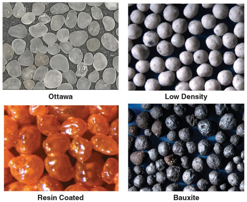
The most common proppant is natural sand that meets very specific physical, mechanical, and chemical requirements. These include size (commonly varying from 100 mesh to as large as 10/20 mesh), sphericity, mechanical-crush strength, and very low solubility in acid. Synthetic proppants are used for special applications, such as deep formations. The more common compositions are ceramics, bauxite, walnut hulls, or even plastics (the latter two are lightweight and used mostly with very low-viscosity fluids). Fig. 4 shows some of the common industrial proppants.
As stated previously, one of the methods of production enhancement is to create a high-permeability fracture that extends deep into the formation. To achieve this, the proppant needs to be carried far along the fracture. Since the specific gravities of most industrial proppants are between 1.9 and 3.6, (much higher than water), the main mechanism for carrying proppant inside a fracture is fluid viscosity. Common fracturing fluid viscosities range from a few tens to several thousand centipoises.
Fracture Design
Engineering computations always precede a fracturing treatment. These consist of calculation of fluid volume and viscosity, injection rate, weight of proppant, volumes of different phases of the job (prepad, pad, slurry, and displacement), surface and bottomhole injection pressure, hydraulic horsepower required at the surface, and the mechanical equipment needed for this.
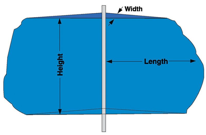
A very important part of fracture design is determination of the fluid volume required to create a fracture with a given length. A hydraulic fracture is usually identified by three dimensions: length, width, and height (Fig. 5). Fracture length itself has two components: created and propped. Created length is the distance between the wellbore and farthest point into the formation. Propped length is the distance between the wellbore and farthest point where proppant has travelled inside the fracture. Fracture width is the separation between the two faces of the fracture. Its value is largest at the wellbore and tapers toward the tip of the fracture. Fracture height is the distance between the top and bottom of the fracture.
The relationships between these parameters and fracture design are as follows. (1) Created fracture length influences total injected volume and fracture width. The longer the required fracture length, the larger the volume of fluid needed to create this length. Longer length also results in a wider fracture. (2) Propped fracture length influences slurry volume, proppant weight, and production increase. Creating a longer propped fracture length requires injecting a larger amount/weight of sand. But this also results in a higher production increase. (3) Fracture width depends on formation mechanical properties, fluid viscosity, and fracture dimensions. Higher-viscosity fluids create a wider fracture. The longer the fracture, the wider it will be at the wellbore. (4) Fracture height is the big unknown and is usually assumed to be constant and related to formation thickness.
The relationship between fracture width and other fracture dimensions has been a subject of debate among fracturing experts for many years. The two basic concepts are those of Perkins and Kern (1961), who relate fracture width to its height, and Khristianovic and Zheltov (1955), who express fracture width as a function of its length. Depending on the choice of basic equations, elaborate computations are needed to calculate various fracturing parameters as functions of injected fluid and formation properties. These are usually done using computer simulations, which are commercially available for this purpose.
The Future: Fracturing Horizontal Wells
In recent years, hydraulic fracturing technology has witnessed major advances, as its use has been the main driver for production from tight oil and gas reservoirs in the US and Canada. In these applications, numerous hydraulic fractures are created along the length of an open or cased horizontal well to gain access to large volumes of the low-permeability reservoir. The number of fractures in cased horizontal wells can be as many as 60 to 70. This number is smaller (but still steadily increasing) in open holes. Most treatments in gas wells are done with water plus a friction reducer pumped at very high rates. In tight oil reservoirs, the fluid usually has higher viscosity and is injected at lower rates. In both applications, the volume of fluid and weight of proppant is at least an order of magnitude larger than what is used in vertical wells. Hydraulic fracturing has played a very important role in enabling the oil and gas industry to meet the energy needs of the growing world. As we are forced to rely on more marginal reservoirs for meeting our energy requirements, the need for better fracturing technology becomes even more pressing. This is best demonstrated by the recent rapid development and deployment of novel fracturing tools and techniques that are specifically suited for horizontal wells.
References
Khristianovic, S.A. and Zheltov, Y.P. 1955. Formation of Vertical Fractures by Means of Highly Viscous Liquid. Proc., Fourth World Petroleum Congress, Rome, Sec. II, 579–586.
Perkins, T.K. and Kern, L.R. 1961. Widths of Hydraulic Fractures. J. Pet. Tech. 13 (9): 937–949. doi: 10.2118/89-PA
