Well integrity and well barriers have been part of the exploitation for oil and gas for nearly a century, with the introduction of the blowout preventer (BOP) in the 1920s. The concept of creating well barrier schematics was inaugurated in Norway in 1992, long before the accidents on the Montara platform in 2009 and the Deepwater Horizon rig in 2010 elevated the global focus on well integrity.
A Common Understanding
Yet there are large variations in the industry’s perception of well integrity and well barriers, despite the daily use of these terms by drilling and well engineers. Well integrity is defined by the Norsok Standard D-010 (Rev. 4, 2013) as an “application of technical, operational, and organizational solutions to reduce risk of uncontrolled release of formation fluids and well fluids throughout the life cycle of a well.”
The definition is so broad that engineers might prefer something that lends itself to a more practical, hands-on description. This is where the well barriers principle comes into play.
If you ask someone what a well barrier is, you will get many different answers. However, it is possible to unify them on the concept of an envelope. The well barrier envelope is the physical system that prevents fluids from flowing unintentionally from the formation into another formation or to the external environment. The envelope is designed to contain this pressurized effluent.
Barrier Envelope Principle
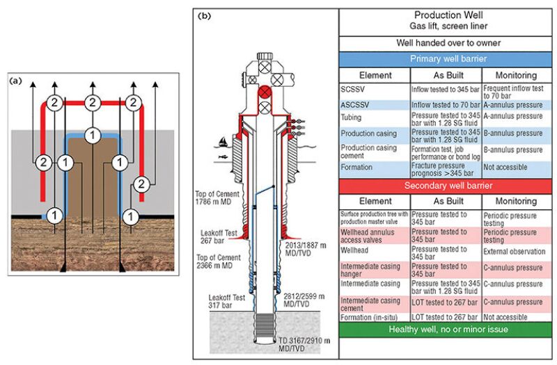
The benefit of using the envelope principle is that we can create two independent envelopes, one outside of the other. We will have primary containment of the pressurized fluid, so that no matter where the pressure might escape through the primary barrier, there will always be a secondary containment behind the primary barrier as a backup (Fig. 1 above). To be consistent and to avoid ambiguity, it is best to define the secondary barrier as the last line of defense rather than barrier No. 2.
Visual, Language Consistency
Following the inauguration of the well barrier schematics in the early 1990s, industry engineers began to make their own representations, typically in Excel, PowerPoint, or Visio. It quickly became apparent that this practice needed to be standardized to prevent others from misinterpreting the originator’s intentions.
The use of strictly controlled component templates or purpose-built information technology (IT) tools has advantages that can help establish a common understanding and perception of barrier definitions. If this is done, well barrier schematics can be created for all situations throughout the life cycle of the well. A consistency in illustration annotation and barrier element listing will further strengthen the common understanding.
These fundamental principles should be applicable to all types of wells worldwide because all well construction is based on the same principle: Drill a hole, run casing, cement the well, and install downhole and surface flow-control equipment. Not every well will be built with two independent barriers, but that fact increases the importance of identifying for stakeholders the single barrier envelope that will contain the hydrocarbons and prevent their escape to surrounding areas.
Aligned With Pressure Curves
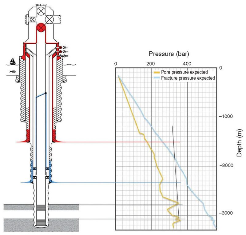
The latest development in well barrier illustration is to align the barrier drawing with the pore and fracture pressure curves of the formation (Fig. 2). This is of considerable help in increasing the stakeholders’ understanding of the challenges and opportunities of the well. Aligning critical barrier points in the well with pore and fracture pressure curves will verify soundness or show weaknesses in the well barrier definition.

Furthermore, a pressure or density gradient line can be imposed on the illustration to show how the formation and surface pressures will affect the hydrostatic load in the well along its vertical depth scale. This can be used to show the reservoir, overbalanced fluid, gas lift, dual-gradient, and managed pressure effects.
Benefits to All Stakeholders
Once a consistent representation of the well barrier definition is established, it becomes much easier to communicate to all stakeholders how the well is safeguarded. Often, well integrity details known to the engineers who have worked directly on well designs are less known by other stakeholders with a role in evaluating the planned well and making decisions in ongoing situations.
A clearly readable illustration is a powerful tool that enables everyone to see the same picture. It becomes easier for people to think through a proposal or a plan, and discussion in the planning or operation stage can be more focused and constructive.
The benefits of using well barrier schematics are
- The speed with which barrier plans can be evaluated
- The common basis of graphics and language provided for discussing well integrity
- The common approach enabled for evaluating a well’s mechanical integrity
- Their usefulness in documenting a variety of wells and operating situations throughout well life cycles
- Their usefulness in providing clear well integrity information when responsibilities are handed over from one stakeholder to another
Global Use of Schematics
The use of well barrier schematics is rapidly expanding among operators worldwide, particularly in areas with strong regulation but also elsewhere without regulatory requirement. Standards such as those of Norsok, the API, and the ISO recommend the preparation of well barrier schematics for different stages of well activity.
As legislators are increasingly recommending the use of barrier illustrations, a number of national, major, and supermajor operators are mandating the use of well barrier schematics as part of their internal requirements or best practices. Operators believe that the adoption of well barrier schematics strengthens their safety profile and can improve their engagement with stakeholders.
Knowledge Sharing, Handover
There are many parties involved in a well over its life cycle, from the planning, construction, operation, and maintenance to its plugging and abandonment. The well barrier schematics play a unique role, being among the few documents that are always present in any well work or evaluation.
A prepared well barrier schematic will provide a document that spells out key elements in the well. It will illustrate the primary and secondary barriers for any well activity, indicate how each barrier element has been or will need to be qualified, and tell how it should be monitored.
Using a dedicated IT tool to prepare and store this work will ensure that all the relevant well information of a company is saved in a logically organized library that is available to all personnel working on a given well at any time.
Personnel should be able to retrieve well barrier schematics and information entered by people in other disciplines, and modify and update it to reflect remedial work or new well activities. A well library is also a useful vehicle for learning how similar issues have been handled in other projects.
As the well responsibility is handed from one party to another, the well barrier schematic offers a clear illustration of its status and how it is safeguarded and will serve as a common core of well information throughout the well’s life cycle. This core document becomes a junction for stakeholders whenever needed and can facilitate proactive work and additional planning.
An understanding of well barrier principles should be fundamental to engineering work in well operations. A good way of summarizing the need to reflect these principles and act accordingly is to be prepared: visualize it, qualify it, monitor it, document it, and communicate it.

