

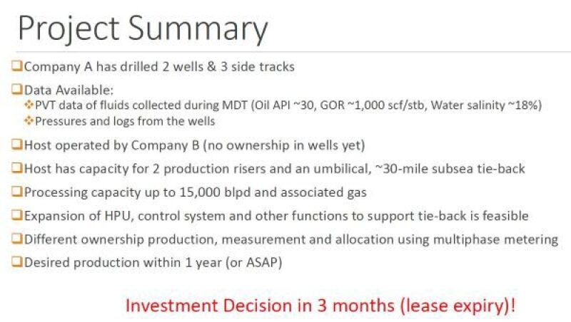
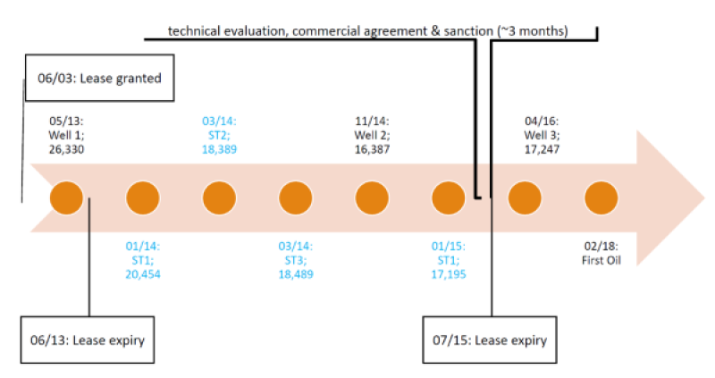
In the summer 2015, Nikhil Joshi, an experienced chemical engineer, and a small integrated team which included subsurface, facilities and flow assurance personnel were faced with a task. They had to look at design simplifications for a brownfield subsea tieback (including flow assurance front-end engineering design) to enable an investment decision. What was different about this project, however, was that they had only 3 months to complete the task.
During an SPE Flow Assurance Technical Section presentation, Joshi, a director for Moulinex Energy, presented a case study “Getting to Sanction in 3 Months—Engineering Perspective,” which detailed how he and his team enabled an investment decision with partner approval.
“My general manager said, ‘I have a great project I want to go forward with’. His mind was made up, but he wanted assurance from flow assurance people,” Joshi said. “Then he said evaluate the project and let me know if you want to go forward. And by the way, I need an answer in two months.”
Simplifications for the project included design to mitigate asphaltene, wax, and hydrate challenges along with a long tieback in deepwater Gulf of Mexico.
A typical timeline getting up to sanction can last anywhere from 12—36 months depending on if it is a brownfield or greenfield site.
“Brownfield is good because you’re sort of stuck in a box, you have to make it fit,” Joshi said. “There isn’t anything new about (getting to sanction in) three months, we (engineers) can get there.”
When looking at the standard design for the project, the team did not do anything out of the ordinary for the project. They looked at the following components:
- Instrumentation (pressure-temperature sensors)
-Bottomhole (max 2 zones individually)
-Upstream and downstream of subsea choke
-possibly at manifolds
- Horizontal tree
-Subsea choke optimized for appropriate well control and drawdown
- Flow loop (potential pigging)—could be optimized (wet/pipe-in-pipe)
-Direct electrical heating considered
- Riser-based connections for future artificial lift
- Frac pack with sand screens
-Sand production not anticipated
- Chemical injection
-Largest umbilical tube limited to 0.75-in. ID
-1x oil-based chemical; downhole
-1x water-based chemical; downhole
-1x methanol— at tree and subsurface safety valve
-Spare tubes based on sparing philosophy
- Flow rate measurements (oil, gas, water)
-Per well: multiphase meter at well jumper
-Per riser: multiphase meter and/or separator
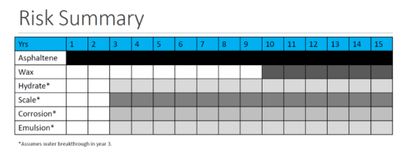
Risk Mitigation
Among the risks, Joshi said asphaltene deposition in the wellbore was the greatest risk with uncertainty in chemical performance and the cost of remediation. All other risk could be mitigated using a combination of chemical and operating procedures as well as remediated with relatively lower costs.
When looking at the simplifications for vapor-liquid equilibrium, Joshi said the project would be primarily oil in the reservoir and there would be a water influx with depletion. The wellbore expected to see a phase change in late life, and the flowline and riser were always expected to be below bubble point. The wells were expected to have a strong water drive and hence, significant water production.
He added that pipe-in-pipe insulation would be unlikely to retain temperatures above wax appearance temperature and that it was impractical for heat retention at lower flow rates.
With wet insulation, temperatures would fall below wax appearance temperature in flowline and riser in late life. Also, the expected wax deposition was low and mitigated using continuous chemical injection.
For the challenges with hydrate, Joshi’s team anticipated water salinity of about 18% based on downhole water samples collected from one of the wells. Steady state flowing conditions were expected to remain outside the hydrate conditions but expected to fall within the hydrate zone during long shut-in and restart. With the long tie-back distance and no storage of dead oil at the host, dead oil circulation would not be feasible and impractical.
Flowline (Single vs Flow Loop)
With the flowline, the team had to consider looking at a single flowline versus a flow loop. The heat loss resulting in wax and hydrate deposition was a possibility, albeit very low based on multiphase flow modeling and analogs. The team considered a single flowline with electrical heating, which was rejected because it could have resulted in a 6-month delay.
A flow loop, which had two flowlines, had its advantages. It could accommodate future upside with more production from additional wells. The standard kit used, meant expedient execution and would meet the project goals and the team had experience in the installation and operation of a flow loop.
Economics
Although the case study was for a brownfield project, Joshi gave an example of deepwater development economics at an accelerated rate as well, showing that improved production economics were possible. The model showed that while its base case for acceleration showed significant uncertainty, and accelerated case has the potential to capture 50% of uncertainty value.
Joshi said stakeholders would have to ask themselves a series of key questions, should they look at his example moving forward. Is fit-for-purpose design for each project necessary? Would such a short timeline be safely achievable, and does a fast approach increase risk?
Overall though, the greenfield and brownfield projects examples shown had better economics with acceleration, even subsea tiebacks. In addition, the commonality in equipment design and operating philosophy improves project economics, but collaboration among operators and supplies are essential.
Getting to what Joshi called a “subsea development utopia” posed the following challenges to the operator, engineering, and supplier community.
- Operators sharing possible development timelines with suppliers to improve supply chain.
- Operators creating a toolkit of subsea equipment, and communicate reservoir performance uncertainty.
- Suppliers having standardized LEGO-like equipment that is multi-vendor compatible.
“It helps to have a small core team with each member having the ability and responsibility to make decisions, said Joshi. “A large team could cover all aspects, but decision making becomes challenging and time consuming.”