Casing drilling is a method by which the well is drilled and cased simultaneously. The small annulus from casing drilling can create a controllable dynamic equivalent circulating density (ECD). Casing-drilling technology enables obtaining the same ECD as with conventional drilling but with a lower (optimized) flow rate and lower rheological properties and mud weight. Frictional pressure loss during casing drilling was evaluated with computational fluid dynamics (CFD). Having accurate models for ECD, including the effects of pipe rotation and eccentricity in the annulus, is essential for success in these challenging jobs.
Introduction
Casing drilling builds on experience gained from drilling liners to bottom in troublesome holes. The technique was implemented for drilling a formation sequence of highly pressured shale followed by a depleted reservoir. The major problem when drilling depleted reservoirs is the narrow operational mud-weight window. With advances in topdrive systems, retrievable bottomhole assemblies, and polycrystalline-diamond-compact bits, the technology enables completing a well by use of casing as the drillstring.
An often-reported benefit of casing drilling is significantly fewer lost-circulation problems. The wellbore-plastering effect that casing drilling offers can enable drilling depleted zones while causing less formation damage. Plastering also enhances pressure containment by smearing the smaller drill cuttings into the pore spaces. The aim of this study was to simulate the casing-drilling operation through CFD modeling to evaluate the combined effect of eccentricity and pipe rotation on the velocity profile of a non-Newtonian fluid.
Approach
Initially, the geometry of casing drilling was constructed for a given wellbore condition. Then, the domain was discretized such that the result would not be grid dependent. A series of cases was designed to compare the CFD model with the analytical solution and validate the discretization scheme. Then, the non-Newtonian-fluid (yield-power-law model) simulation was run. Thereafter, an effort was made to analyze the effect of eccentricity and pipe rotation on the yield-power-law fluid.
Assumptions
In drilling operations, continuous fluid circulation through the annulus results in steady-state flow. In the shallow top-hole section, the fluid can be treated as an incompressible fluid. The simulated laminar-flow regime verified the CFD results with the analytical solution. It was assumed that a single-phase fluid flows through the annulus and that the pipe geometry provides a uniform concentric annulus along the test section.
For simplicity, the effects of drill cuttings were neglected in the simulation to be able to validate the CFD results with the analytical solution. Initially, the casing was treated as stationary (no pipe rotation) with a no-slip condition at the walls (both inner-pipe and wellbore). The pipe and the wellbore were assumed to be smooth. Also, the geometry was held uniform along the pipe (i.e., the effect of tool joints on pressure loss was neglected). The pipe section was considered to be 5 or 10 m long.
Methodology
Analytical solutions are faster and more convenient than numerical techniques, but they lack generality in most cases. To verify the accuracy of a given numerical technique, its results can be compared with the corresponding analytical solution, if available. To verify that the velocity profile was fully developed, the required entry length of the pipe in the test section was estimated. Entry length is the pipe length at which the centerline velocity is 99% of the fully developed centerline velocity.
Computational Mesh. The accuracy of the steady-state numerical solution constitutes a base case for other complicated geometries for which no analytical solution is available. Numerical-method validation was carried out by comparing CFD results (i.e., pressure gradient and velocity field) with results of a narrow-slot analytical solution, as shown in Fig. 1.

The annular gap between the inner pipe and the wellbore wall was configured as a concentric geometry and as an eccentric layout. To analyze the effect of eccentricity on pressure loss, five cases were considered. Initially, an optimization process was performed to match the best meshing size with the lowest error. Several simulations were run with different mesh sizes, and the results were compared with the narrow-slot analytical solution of a non-Newtonian fluid. To capture the velocity field in the region of high shear rate (i.e., close to the wall), two inflation layers were defined within the cross-sectional area of the pipe. Discretization of the domain along the tangential direction was selected in the range of 200 to 300 divisions. It was confirmed that the numerical results were consistent for 5- and 10-m pipe lengths.
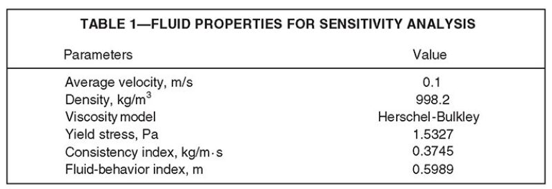
Boundary Conditions and Fluid Properties. To simplify analysis sensitivity, it was assumed that the fluid flows in isothermal and laminar conditions. At the inlet, a constant fluid velocity equal to the bulk-fluid velocity along the pipe was specified and the boundary condition at the outlet was set to zero static pressure. To initialize the CFD analysis, the fluid properties of a yield-power-law fluid were assumed, as given in Table 1.

Verification of CFD Results
No analytical solution was available for flow of a yield-power-law fluid in an annulus section. Therefore, the authors used CFD simulation to generate the results for the cylindrical geometries. The results of the CFD solution were verified with the narrow-slot-approximation solution for a yield-power-law fluid. A sensitivity study of CFD simulation was performed by selecting different rheological values to examine the accuracy of the computation and meshing properness.
Values of yield stress τy=0.833, 1.183, and 1.533 were used to quantify the error magnitude of CFD calculations. The simulation was performed for each configuration (concentric geometry), and the results were compared with the narrow-slot analytical solution. Error values for all cases were reasonable, with the largest error <3%. The frictional-pressure-drop curves showed a similar pattern for the values of yield stress. When the yield stress increased, the frictional pressure drop increased. The meshing scheme was nearly insensitive to the values of yield stress when a good match existed between the CFD result and the analytical solution. There was a similar pattern in pressure drop for the three selected values of yield stress.
Eccentricity Effect
The governing equations become complicated as the inner pipe (casing) becomes offset to an unknown value. An eccentricity value ε describes how off-center a pipe is within another pipe or the open hole. A pipe is considered concentric (0% eccentric, ε=0) if it is perfectly centered in the outer pipe or hole. The eccentricity of the inner pipe was increased to investigate the effect of eccentricity on frictional pressure loss. Five cases were studied: ε=0.1, 0.3, 0.5, 0.7, and 0.9. Note that the meshing scheme of the eccentric pipe should be repeated to discretize the wider-gap region properly. The meshing configurations shown in Fig. 2 are for a radius ratio (inner-pipe outside radius/borehole-wall radius) of 0.76 and ε values of 0.1, 0.5, and 0.9.

Monitoring the velocity profile in the horizontal cross section (A–A′) reveals that the fluid velocity is higher in the wider gap and lower in the narrow region. The geometrical configuration reduced the overall effect of wall friction on the fluid domain. Therefore, it is expected that increased eccentricity would reduce the pressure drop. The effect of eccentricity on pressure loss is more dominant in the range of ε=0.2 to ε=0.8. In general, it was concluded that as eccentricity increases, the pressure drop along the annulus decreases.
Pipe-Rotation Effect
The inner pipe was rotated at 20, 30, 40, 50, and 60 rev/min by selecting the inner-pipe boundary condition as a moving wall. A velocity-ratio parameter ζ can be defined to specify the flow regimes in the annular space. The ζ for these geometries was set between 1 and 10. That range specifies a mixed-flow regime (i.e., between axial-dominated and rotation-dominated flow).
A pressure-drop pattern, similar to a function of radius ratio, was recognized. Pipe rotation promoted a shear-thinning response to reduce the apparent viscosity exhibited by a yield-power-law fluid. The effect of pipe rotation on frictional pressure loss was explained by examining the velocity profile across the annular gap. For the first configuration (radius ratio=0.7), the effect of pipe rotation was distributed almost along the radial direction. The plug zone disappeared as pipe rotation was increased, which was accounted for by the shear-thinning properties of a yield-power-law fluid.
Simulating Field Data
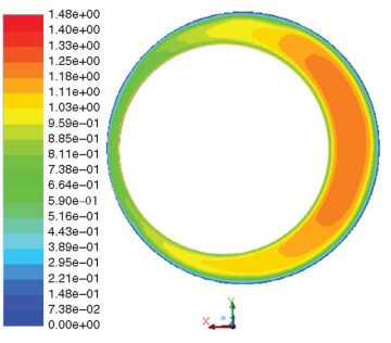
The geometry of the casing-drilling operation corresponded to the second eccentric case, with a radius ratio of 0.764. The Fann-viscometer data were converted to corresponding shear-rate and stress values by use of appropriate conversion factors. The results then were recognized as the rheological properties of a yield-power-law fluid. Those fluid properties were used to match the CFD prediction with that of field data. The frictional pressure drop for field data was reported as 135 Pa/m, which could be obtained from ECD data. Initially, an attempt was made to obtain the pressure drop of the concentric geometry without pipe rotation. The CFD yielded a 330-Pa/m pressure drop for the given geometry. The next step was to implement the effect of pipe rotation, yielding a 178-Pa/m pressure drop. To match real data, an attempt was made to determine the geometry by use of estimated eccentricity values. The closest match of pressure-drop prediction to field data yielded a possible eccentricity value. Increasing the casing eccentricity to a value of 0.9 reduced the pressure drop. The combination of pipe rotation and eccentricity yielded a 151‑Pa/m pressure drop. The final velocity distribution is shown in Fig. 3. The discrepancy between simulation and field data may be attributed to the following constraints: Tool joints were not included in the geometry, the walls were treated as a smooth surface, and the effect of drill cuttings on the flow regime was ignored. Note that the wellbore shape might not be circular, as envisioned in this model. Also, assuming a zero-slip condition may not be appropriate for real application. Thermal effects and fluid compressibility may contribute to overestimating pressure loss also.

Conclusions
- Including eccentricity in the simulation indicated that a general pattern can be recognized as a function of pipe eccentricity for yield-power-law fluids.
- Increasing pipe rotation helped reduce the frictional pressure loss in the annulus.
- Comparing the results of CFD simulation with field data in a stepwise manner indicated that the casing may have been off-center in the wellbore.
- The effect of wellbore-wall roughness should be considered to yield a more-realistic estimation of the frictional pressure loss. Several pipe joints should be included along the test section to study the effect of tool joints on pressure losses.
This article, written by Dennis Denney, contains highlights of paper SPE 166103, “Evaluation of Annular-Pressure Losses While Casing Drilling,” by Vahid Dokhani and Mojtaba P. Shahri, SPE, University of Tulsa; Moji Karimi, SPE, Weatherford; and Saeed Salehi, SPE, University of Louisiana at Lafayette, prepared for the 2013 SPE Annual Technical Conference and Exhibition, New Orleans, 30 September–2 October. The paper has not been peer reviewed.
