
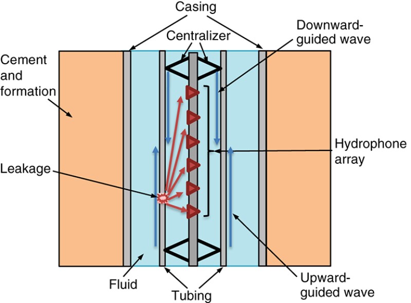
Leaks in wellbore tubulars emit acoustic waves in the borehole that can be captured by a hydrophone array. Processing the array data yields location and energy level of the wellbore leaks; however, the hydrophones also may capture other coherent noise propagating as guided waves along the borehole. The complete paper describes an approach to estimate and subsequently remove the guided-wave noise from the hydrophone array data to improve the accuracy of leak-source locations. Estimating the propagation direction and amplitude of leak-induced guided waves aids logging operations to locate a leak source efficiently.
Noise Logging and Well Integrity
Well integrity has become a focused area for most operators given the long life cycle and complex structure of a wellbore.
×

Continue Reading with SPE Membership
SPE Members: Please sign in at the top of the page for access to this member-exclusive content. If you are not a member and you find JPT content valuable, we encourage you to become a part of the SPE member community to gain full access.