As exploration and production (E&P) projects move into more unique territories, operating companies must evaluate their projects’ infrastructures and devise strategies to sufficiently prepare for a growing energy demand. These strategies may take the form of significant upgrades to existing facilities or the construction of new facilities altogether.
At the 2015 SPE Annual Technical Conference and Exhibition, representatives from small private and state-owned operating companies discussed the challenges they faced with facilities design and construction, both onshore and offshore. This feature examines some of the strategies that were taken to handle those challenges.
Pacific E&P: In-situ Combustion Pilot Project
Last year, Pacific E&P finished work on a pilot for the first in-situ combustion project in Colombia, at the Quifa oil field located in the eastern part of the Llanos basin.
Pacific E&P had five main objectives with the pilot. First, it wanted to evaluate the applicability of in-situ combustion in the heavy oil field. Second, it wanted to assess the impact of the reservoir heterogeneities on the process performance. Third, it sought experience and accuracy on the simulation and analytical models developed during the operation. Fourth, it sought to identify solutions for possible operational problems that may arise during the project such as emulsions and corrosion. Fifth, it wanted to learn enough about in-situ combustion technology to eventually move to a fieldwide implementation strategy.
The Quifa oil field is a monocline structure slightly deformed by synthetic normal faults of small displacement. Its primary producing formation is the Carbonera basal interval of the Carbonera formation, a succession of sandstones and shales with fine to coarse grains and porosity between 25% and 33%, permeability ranging from 5 to 10 darcies, and a net-pay thickness ranging from 7 ft to 50 ft. The oil gravity in the field ranges from 13 °API to 14 °API, and the gas/oil ratio is 7–8 scf/bbl. The oil in place is roughly 1.5 billion bbl.
Eduardo Lima, senior vice president of project development at Pacific E&P, said the company’s lack of experience in this area led it to utilize any available resource it could find to help with the design of the on-site facilities.
“This was the first [in-situ] combustion project implemented in Colombia. We had no idea about how the fluid composition was going to change, or any experience from a similar project. We relied on combustion tube tests. We had also analytical modeling, simulation, and data from different projects worldwide. This was the main information that the project engineers used to start designing the facilities,” he said.
Operated over a 32-month period from November 2011 to July 2014, the project involved the use of a modified inverted-nine spot pattern, in which the central injection well was surrounded by nine producing wells. The project team fitted each well and most of the surface equipment with pressure and temperature devices. It also developed real-time monitoring and visualization for proper surveillance of the pilot operation (Prieto et al. 2015).
The company based the conceptual design of the project on the criteria needed to satisfy the critical variables of the process like temperature, pressure, and fluid composition. It had to account for the three phases in which the project would be executed: cold production, preheating, and hot production.
The hot-production stage had the biggest impact on the facility design. Lima said Pacific E&P had to consider the use of oil dehydration units that were capable of handling an oil composition with water content within commercial specifications. It also had to include units for the treatment of acid water and the removal of hydrogen sulfide (H2S) from the gas stream before venting.
“We kept in mind that even though the combustion tests never showed any H2S, we knew were going to have some. So, we kept that in mind when dealing with the mechanical integrity and safety of the operation,” Lima said.
The design and operation of the surface facilities took into consideration the effect of in-situ combustion on the mechanical integrity of the installations and the environment. Adequate piping class specification was implemented along with proper health, safety, and environment practices that complied with local and international standards. The installation of early detection systems helped the pilot operate within regulations and in safe conditions.
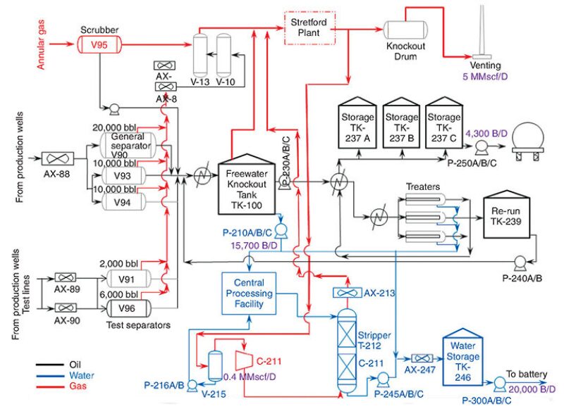
Fig. 1 illustrates the general layout of the production facilities. The gas produced from the well annular was directed to a test separator and mixed at the exit with the gas that came from the general separators. The total gas stream entered the V-13 and V-10 separators for liquid removal before being transferred to a Stretford plant.

The resulting sweet gas was directed to a knockout drum to remove liquids and then to a venting tower. A part of the sweet gas exiting the Stretford plant was directed to a stripper tower to contact the acid water. The resulting sour gas was then redirected to the Stretford plant.
The design of the water processing system factored in the formation of acid water. The water was separated from the oil within a freewater knockout (FWKO) tank, and the treaters were directed to corrugated plate separators. After that, they went to the stripper tower in order to normalize the pH of the acid water, which normally has a value between 7 or 8 but was as low as 3 in some wells. The sweet water coming from the stripper tower continued into the skim tank, and the water was transported to a distant central processing facility to continue its treatment.
The liquid stream was sent to the FWKO tank to remove the free water. The emulsion coming out of this tank continued to the thermal treaters after passing through an oil/oil exchanger and a steam/oil heat exchanger. The dehydrated oil from the treaters was then directed to storage tanks, and crude oil from the treaters that were out of specification was sent to a rerun tank.
The surface facilities were equipped with sensing devices for real-time surveillance, mainly pressure, temperature, and flow rates. A supervisory control and data acquisition (SCADA) system was implemented with all the required software, hardware, and control systems.
Lima said the pilot project helped Pacific E&P gain experience in the design, construction, and management of an in-situ combustion process, and this experience will be useful to the company as it develops future projects. The implementation of enhanced oil recovery projects of this type helped the company better understand the relationship between surface and subsurface process.
KOC: Onshore Facilities Modernization
To handle the higher production demands stemming from increased water cuts in reservoir fluids, the Kuwait Oil Company (KOC) underwent a modernization project for its numerous onshore facilities, an initiative that involved several facility upgrades.
Separation was one area specifically targeted for improvement. KOC evaluated the water-handling capacity of its separators, desalters, and associated equipment and installed three-phase separators. Some two-phase oil/gas separators were converted to three-phase separators with water boots. The company tried and installed several oil/water treatment systems, including corrugated plate interceptors, assorted plate interceptors, dissolved air flotators, and induced gas flotation units. It also installed intake header extensions (Mirza and Al-Kharqawi 2015).
“We have gone through all types of water and oil treatment and separation facilities,” said Babar Mirza, a senior project engineer at KOC. “Right now we believe it is better to have large tanks that will have a greater retention time for separation. That is what is working for us.”
Increased safety concerns led to the relocation of the underground piping systems in the company’s gathering centers in Burgan, Magwa, Ahmadi, and North Kuwait. The pipes were moved above ground, and the rotating equipment involved in crude oil and gas export, specifically the pipes and compressors, was replaced with variable speed motor-driven bespoke centrifugal pumps and compressors. The old rotating equipment is used as a standby unit.
When designing the centrifugal pumps, KOC faced issues with the design margins. A desalter feed pump at one of the company’s gathering centers tripped on a motor overload during startup. The company determined that the motor overload was the result of the excessive flow caused by an overspecified pump head. Throttling the pump discharge valve reduced the pump flow and fixed the issue.
Mirza said it was important to select design margins for centrifugal pumps that do not overspecify the pumps themselves. He said overly specified pumps can negatively affect the performance of the pump impeller, increasing wear and tear and reducing equipment life.
“You might have problems with unnecessary erosion and wasting power. So you cannot oversize your pumps too much. But how much? That depends on the power requirement, the pump capacity, and the head,” Mirza said.
Production demands also led KOC to adopt improved oil recovery techniques in its operations. This led to the installation of electric submersible and sucker rod pumps at its facilities in northern, western, and southeastern Kuwait. In addition, the company began using a stronger steel grade, API-5L Grade X52, for its flowlines and mandated the installation of surface safety valves.
The company recently installed multiport selector valves and field manifolds at its facilities in southeastern Kuwait.
Like Pacific E&P, KOC had to account for the presence of H2S in its fields, specifically the Minagish and Umm Gudair fields in west Kuwait and the Jurassic fields of northern and western Kuwait. With crude oil and gas in these areas turning sour, the company built a new plant in western Kuwait for sour gas sweetening, and another plant is currently under construction (Mirza and Al-Kharqawi 2015).
The new treatment facilities for the sour hydrocarbon fluids were equipped with steam-/hot-oil-heated crude stabilizers and gas sweetening agents such as amine. Other gas sweetening equipment, such as sour gas scrubbers, contactor/absorber towers, coalescing-type gas/oil filters, regenerators, reboilers, compressor trim coolers, and glycol dehydrators were also installed.
As part of the revamp of one of its early production facilities, EPF-50, KOC refurbished the contactor column internals. These internals included the amine contactor, refrigerator still column, glycol contactor, and crude stabilizer. The company replaced its conventional bubble cap-type tray with a high-efficiency proprietary valve-type tray arrangement and proprietary vane-type gas inlet devices.
Some of KOC’s larger infrastructural improvements involved its Telemetry System Project. The company aimed to increase gas revenue and reduce carbon dioxide emissions by reducing flaring by more than 10% over a 5-year span. In 2009, ABB equipped KOC’s gas and condensate networks with a SCADA system that controlled each asset in the network and measured the gas and condensate volumes flowing through the pipelines.
The system detects leaks, measures flaring, and calculates potential revenue loss. It also allows for the remote shutdown of pipelines and the transfer of gas across networks. One of its more crucial features, though, is its ability to provide real-time information on asset performance to the company’s management through reports, messages, and alarms, thus allowing for a more precise tracking of gas flow (ABB 2010).
PTTEP: Minimum Facility Platform
Petroleum Thailand Exploration and Production (PTTEP) is developing a minimum facility platform (MFP) to access a small amount of reserves. Located in the Arthit field in the Gulf of Thailand, these reserves cannot be commercially developed with a conventional wellhead platform (CWP). Scheduled to start up in 2017, the MFP will have a smaller size and a lower construction cost, which the company hopes will ensure economic viability.
Located approximately 150 miles northeast off the southeast Thai coast, Arthit sits in a relatively shallow water depth of 262.5 ft. PTTEP’s existing facilities in the field include processing, flare, and living quarters platforms; a wellhead platform with a bridged link to the processing platform; 31 remote CWPs; an 8-in. condensate pipeline from the processing platform to a floating storage unit in the nearby Bongkot field; and a 42-in. gas export pipeline connected to onshore facilities through an export trunkline.
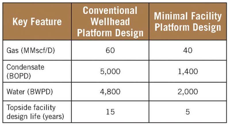
Table 1 highlights the differences in design inputs between the MFP and the CWP. Compared to a conventional platform, Chanwith Buntoengpesuchsakul estimated that the project team could achieve significant cost reduction by building an MFP. Buntoengpesuchsakul is a mechanical and piping engineer at PTTEP.

However, in order to achieve those cost savings, PTTEP needed to design its new platform with a fit-for-purpose approach. By building a platform with a shorter topside facility design life, the company could optimize the material selection, corrosion allowances, and anode calculations, which would then allow for a reduction in material quantity for the wellhead platform (Chanwith et al. 2015).
Buntoengpesuchsakul said the company was able to design a platform with a short life expectancy because of the smaller size and shallow depth of the reservoir.
“The size of the reservoir allowed us to reduce the cost and the size of the platform. The reservoir data that we received told us that the life expectancy was only 5 years. It would deplete faster than at a conventional reservoir depth,” he said.
The MFP will tie back to the existing CWP through a subsea pipeline. PTTEP will use a mobile pig launcher for subsea pipeline pigging and designate provisional space for a future pig receiver. The platform will rely on solar power with a battery backup that can accommodate up to 96 hours of usage for the process control system and 192 hours for the safety facilities. However, the project team left open the possibility of using a diesel engine generator to provide alternating-current power for lighting and small power loads (Chanwith et al. 2015).
In addition, the MFP had to meet the following production and operation requirements:
- The remote wellhead platforms must be automated for operations that are normally unmanned, or operations that require personnel only for restocking consumable fluids, maintenance, and restarting after an emergency shutdown.
- The main equipment must be located on the lower deck of the platform. This includes the booster compressor, test separator, manifolds, wellhead control panel, pig launcher, future pig receiver, and a SCADA system.
- Remote control of all systems from the processing platform must be enabled.
- Maintenance and other activities requiring personnel on site would be conducted by campaign and not routine platform visits. The frequency of visits to the platform should be no more than every 4 weeks, and nighttime working on the platform is to be limited.
- A liaison between the project team and the well services team is required to fully define the requirements for the crane, wellhead control, power supply, and deck space.
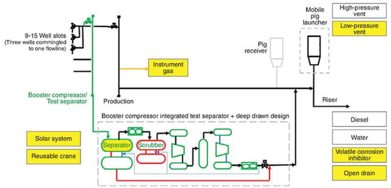
Fig. 2 shows the schematic for the MFP. The project team decided to provide between 9 and 15 well slots for the wellhead platform, compared to the 16-well slot average for conventional reservoirs in the Gulf of Thailand (Chanwith et al. 2015).

A conventional test separator at the wellhead platform will separate and measure the flow rates of the gas, produced water, and condensate from the well production fluid. If the flowing pressure from the wellhead is so low that the well production fluid cannot flow to the surface, a conventional booster compressor will be used to boost the pressure.
The project team integrated the conventional test separator system into a new booster compressor system. Chanwith et al. state that this is because the project team felt it was redundant to operate a two-phase separator system in a booster compressor and a three-phase conventional test separator at the same time.
In this integrated system, which the project team called a “booster compressor integrated with test separator function,” a gas flowmeter measures the gas flow from the gas output section while a liquid flowmeter measures the liquid flow. A water-cut meter measures the liquid flow of each phase between water and condensate from the liquid output section of the blowcase body.
The project team aims to achieve cost reduction through its choice of structural parts and the design of its pipeline system. It estimates a 20% decrease in overall platform deck area compared to a CWP, which may lead to a 30% overall cost reduction. With smaller topsides facilities, the transportation and lifting of the MFP can be completed in a single run.
Installing smaller-diameter pipelines also helps lower costs. Normal pipeline sizes for a PTTEP facility in Arthit are 12 in. and 16 in., but reducing the sizes to 10 in. and 12 in. eliminates the need for concrete weight coating. In addition, the project team replaced the carbon steel seamless pipe typically used for its pipelines with cheaper electrical resistance welding pipe.
For Further Reading
SPE 174740 Minimum Facility Platform for Sub-Commercial Reservoirs in the Gulf of Thailand by B. Chanwith, P. Pheerasak, and S. Thitinun et al., PTTEP.
SPE 174747 Key Engineering Highlights of Facilities and Equipment for Oil & Gas Production by B. Mirza and F. al-Kharqawi, Kuwait Oil Company.
SPE 174970 Design and Operation of Production Facilities of the Quifa Field In-situ Combustion Project by H. Prieto, E. Lima, and M.R. Gaviria et al., Pacific Rubiales Energy.
ABB. 2010. ABB solution helps Kuwait Oil boost efficiency, http://www.abb.com/cawp/seitp202/c05c8cabda434300c125774c003a0825.aspx (accessed 6 November 2015).

