
During the design, implementation, and operation of the Cascade and Chinook (C&C) field development project in ultradeep water in the Lower Tertiary play of the Gulf of Mexico (GOM), the technical limits of single-trip multizone (STMZ) frac-pack systems were pushed to depths greater than 27,000 ft using high fracture rates and high-strength proppants; knowledge was gained from ultrahigh-pressure (greater than 20,000 psi) tubing-conveyed perforating systems; and well-design criteria suitable for high-drawdown (more than 12,000 psi) production operations were demonstrated.
Introduction
The C&C development plan in the GOM is one of the most technologically challenging and complex projects ever implemented by Petrobras. This project uses the first floating production, storage, and offloading vessel in operation in US waters at a water depth of 8,200 ft. The C&C subsea infrastructure considers the use of subsea manifolds, rigid flowlines, pipe-in-pipe pipelines, and free-standing hybrid risers. These two fields are 15 miles apart and share several characteristics such as depth, lithology, and reservoir similarities. The Wilcox 1 (Eocene) and 2 (Paleocene) sands belong to the Lower Tertiary geologic period and are part of the latest exploratory frontier in the GOM. At least 12 discoveries have been made in the Lower Tertiary, holding a potentially recoverable volume of several billion bbl of oil, highlighting the importance of this technology development for the industry. These reservoirs are characterized by a considerable thickness of intercalated sandstones and shales. The reservoirs show low horizontal permeability (less than 100 md) and poor vertical communication between sand layers. Other characteristics include a very high static formation pressure, a maximum temperature of 256°F, and a low gas/oil ratio. The produced oil has carbon dioxide concentration in the gaseous phase of less than 1.5%, and there is no evidence of hydrogen sulfide contamination.
Drilling Design
The casing design was based on delivering an 8½-in.-internal-diameter casing at total depth (TD) to accommodate the completion design. In this design, each string is run to its approximate design limit to maximize leakoff-test (LOT) values. One of the most important strategies of the C&C wells was the elimination of the 11⅞-in. liner, which prevents achieving adequate circulation rates for a successful primary cement job on the 10⅛‑in. production casing.
In addition to the extreme differential pressures at the sandface depth, another critical point for the well design was the annular-pressure-buildup (APB) risk mitigation. APB analysis indicates very high pressures developing in all annuli in the producing wells. Rupture disks are used to mitigate APB effects on the large casings (22- and 16-in.), and other operational measures are taken to mitigate the effects of APB in the A-annulus.
Drilling Operations
The riserless drilling phase of the wells includes jetting the 36-in. casing, drilling out with a 26-in. bottomhole assembly to 12,000 ft, running the 22-in. casing with the high-pressure housing, and cementing it in place. The blowout preventer (BOP) and riser are run, latched, and function/pressure tested at the mudline. The next three drilling phases require operations with hole openers, which has been a major source of nonproductive time in C&C project drilling operations. Abrasive sands in the Miocene section create vibrations, which are exacerbated with hole-opener geometry, resulting in slow rate of penetration, premature wear, logging-while-drilling failure, and a potential for twistoffs. During the drilling operations of the first wells, losses were encountered in weak zones below the 22-in.-casing shoe. Proper mud-weight management and upgrading of the 18-in.-casing phase from contingency to a planned phase were successful in mitigating the risk of major losses.
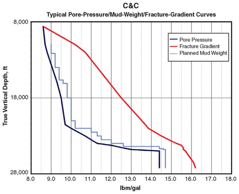
The main driver in the well design is to reach adequate LOT values in each hole section to safely reach the next phase of drilling to TD. The most important depth target phase in the C&C wells is the drilling of the 16½-in.-outer-diameter open hole before setting the 14×13¾-in.-casing string. The depth of the 14×13¾-in.-casing shoe should be within the Oligocene pressure ramp, approximately 1,000 ft above the top of the Wilcox 1 formation. Fig. 1 displays the typical pressure ramp and pore pressure/fracture-gradient profile for the C&C fields.
Rig operations switched from drilling to completing after the production casing/liner was run. After the production casing/tieback was run and cemented and a cement-evaluation log was run, the synthetic-oil-based drilling mud was displaced by a zinc-bromide-based completion brine. Following the displacement operation, the BOP stack was removed and a 15,000-psi horizontal tree was installed on the wellhead by use of a cable with a heave-compensated winch from a multiservice vessel before reconnecting the BOP stack to the top of the tree.
STMZ System
An STMZ completion system was selected because of its significantly reduced installation time. Extensive fracture modeling showed that the reservoirs could be stimulated adequately with three fractures. It was anticipated that it would take 30 days and eight round trips in the well to install conventional three-zone stacked frac packs, but an STMZ system was estimated to take 14 days and three round trips to install, a significant savings of time and money.
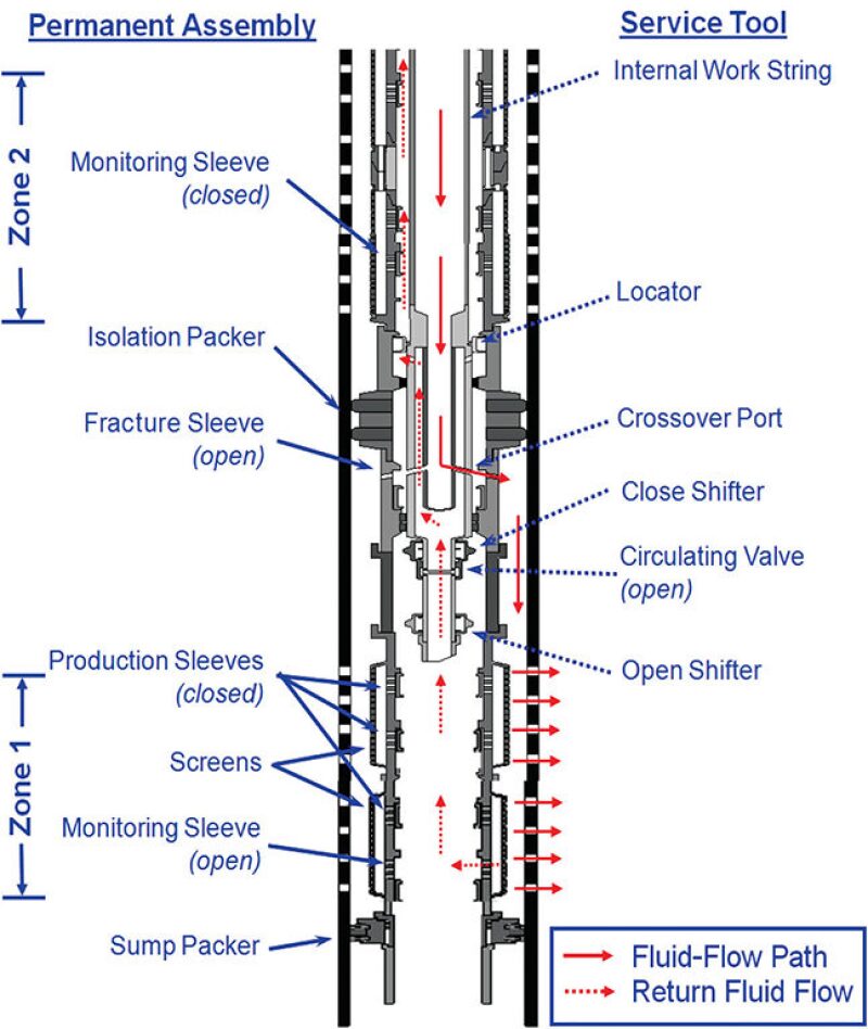
The general procedure for running an STMZ system is as follows. The sump packer is logged on depth and set by electric line to establish a base for the system. Then, all zones are perforated with a tubing-conveyed perforating system. Following perforating, a deburring run is made to remove any perforation burrs that might damage the packer elements of the STMZ system. Finally, the entire STMZ system, with screens, packers, and fracture-service tools, is run in the well. Once on depth, all the packers are set hydraulically. Starting with the lower zone and moving uphole, each of the intervals is fracture stimulated. In each zone, a monitoring sleeve is opened to allow observation of the bottomhole treating pressure and to allow taking of returns to induce a screenout, if necessary. Following the fracturing operation, the fracture sleeve and monitoring sleeve are closed and tested before moving up to the next zone.
Fig. 2 shows a schematic of the downhole assembly with the service tool in the fracturing position. This configuration was used in the first two wells that were completed in the project. Before the completion of the third well, the STMZ system was modified so that after a fracturing job, the fracture sleeve and the monitoring sleeve are closed with upward movement only, without having to break a connection at the surface. This modification was achieved by extending the inner work string and adding a second closing shifter. Before this change, the service tool had to be stripped down in the well by as much as 200 ft to close the monitoring sleeve.
After all the zones are fractured, the service tool is pulled out of the well, mechanically isolating the well from the reservoir with all the sleeves closed. An isolation string is then run in the well. This isolation string consists of an isolation packer, an isolation ball valve, and shifters on an inner work string that open the integral production sleeves (two or more in each zone) located in the screen assemblies. After the isolation assembly is in position, the isolation packer is set hydraulically. Upon release of the -isolation-packer-setting tool, the isolation ball valve is closed, providing mechanical isolation to the reservoir. This isolation ball valve remains closed until after the upper completion is installed and the crown plugs have been set in the horizontal tree. A series of pressure cycles is then applied down the tubing to open the isolation ball valve.
Frac-Pack Designs
The C&C wells (three wells) were completed in the Lower Tertiary formation with an average of three propped--fracture treatments in the Wilcox 1 and 2 zones. The challenge is to complete this very thick interval while also avoiding the water contact and avoiding placement of perforations near the identified faults crossing the pay zone.
Pseudosteady-state fold-of-increase calculations were used to give a preliminary estimate of the desired fracture length/conductivity. These calculations used values for net pay and permeability from the petrophysical analysis. The initial results suggest a desirable fracture of 150-ft half-length, with 2-lbm/ft2 or greater proppant coverage with high-strength bauxite proppant. This would provide three times the deliverability of an unstimulated well. Assuming simple radial fracture geometry, this implies a job size of 170,000 lbm of proppant for each fracture treatment, with three to four treatments needed to stimulate the entire formation thickness. Bauxite proppant was ultimately selected because of its strength and its ability to maintain good fracture conductivity in high-confining-stress environments.
Isolation Assembly and Upper Completion
The isolation assembly had unique shifting profiles in the production sleeves of each interval. This allowed all the mechanical production sliding sleeves to be opened simultaneously to minimize completion-fluid loss to the formation. It was important to validate the opening of the production sliding sleeves, and to confirm that the wellbore was isolated by a fluid-loss-control device, before the deployment of the upper completion. The mechanical shifting tools were spaced out carefully along the concentric inner string to minimize fluid loss within the time the first and last production sleeves were opened. This took place approximately 160 ft from the point where the isolation packer reached its final setting depth. Once all the production sleeves were opened mechanically, the seal-bore isolation packer was set hydraulically. The ball valve was closed as the packer-setting tool was retrieved (with the ball-valve-closing tool hanging below it). It is important to note that the ball valve was deployed separately from the frac-pack screen assembly in order to increase the reliability of this device by eliminating its exposure to debris during frac-pack operations.
The upper completion for the C&C wells was designed to achieve multiple goals including reservoir, flow assurance, and regulatory requirements, while eliminating the need for downhole through-tubing wireline or slickline operations. To facilitate the final space out of the upper completion, a 10-ft seal assembly was stabbed into a 40-ft seal-bore receptacle located in the isolation assembly (below the seal-bore isolation packer). The production packer also provided a way to anchor the production tubing and minimize seal movement caused by temperature changes throughout the production life cycle of the C&C wells.
This article, written by JPT Technology Editor Chris Carpenter, contains highlights of paper OTC 24179, “Drilling and Completing Cascade and Chinook Wells: A Design and Execution Case History,” by Flavio Dias De Moraes, Petrobras; Oswaldo Moreira, Petrobras America; Ziad Haddad, FOI Technologies; Scott Ogier and Jonathan Shipley, SPE, Cherokee Offshore Engineering; Mauricio Rebelo, Petrobras; and Fernando Gama, Petrobras America, prepared for the 2013 Offshore Technology Conference, Houston, 6–9 May. The paper has not been peer reviewed. Copyright 2013 Offshore Technology Conference. Reproduced by permission.