

An operator requiring an offshore coiled-tubing (CT) intervention offshore Brunei in the South China Sea encountered challenging monsoon weather conditions as well as limited and aging offshore facilities. Innovative technologies from various applications, including a full-catenary CT system, a dynamic-positioning (DP) vessel, a knuckle-boom crane, and a heave-compensated gangway, were combined to provide the operator with a successful solution for CT-intervention improvement.
Introduction
Operations were performed in the Darussalam offshore waterflood oil field. The field’s average sea depth was approximately 30 m of water, and the field was approximately 70 km northeast of Seria. A central field complex had living quarters for approximately 160 personnel, gas lift and compression facilities, and water-injection facilities. Waterflooding was a significant factor supporting the hydrocarbon-production levels, and, to increase hydrocarbon production, water-injection improvements were required.
During monsoon season, the conventional well-intervention vessel had a limited operating envelope because it was unable to hold in a rough sea position and lacked emergency-disconnect CT and hydraulics-hose systems and a compensated gangway. These limitations made safe operation impossible during monsoon season. Once the operating rate was deemed limited, stimulation (acidizing) activity was postponed, thus affecting production results. However, with new concepts of intervention, the vessel was able to continue operating during rough sea conditions safely and more efficiently.
New-Concept Stimulation Vessel
DP Vessel. The well-intervention/stimulation vessel was newly built; it was equipped with a DP Class 2 system, which included antiroll tanks and a computerized ballast-control system. This vessel was designed to operate year-round in typical seasonal weather of southeastern Asian waters. In the coastal waters off Borneo Island, typically in Brunei Darussalam, the significant wave height during the monsoon period from November to February was approximately 3.5 m. During the remainder of the year, wave height was between 0.5 and 2.5 m. However, during the occurrence of storms offshore, the significant wave height could reach 3.5 to 4.0 m.
DP vessels were capable of responding to dramatically changing weather conditions by helping ensure that the DP system interpreted environmental data and allowed the operator to hold or change the vessel’s position accordingly. This capability allowed the vessel to maintain position and remain on station at a safe distance adjacent to a platform while performing intervention operations. Typically, a DP footprint existed of the distance the vessel operated from within a central axis. Each DP vessel had referencing systems, depending on the operator or end-user requirements. The vessel discussed in this work had three referencing systems to provide a redundancy so that the DP-system computer could ascertain the vessel’s exact location as well as the magnitude and direction of environmental forces affecting its position. If changes in position were detected by the computer on the basis of the parameters provided by the referencing system, the DP computer provided automatic command signals to the propulsion systems to increase or decrease thrust and direction heading of the thrusters (in the case of azimuth thrusters) until the desired set location or direction was achieved. This was performed without operator intervention, although a DP operator was fully aware of what the system was doing while he or she monitored the operation.
Another advantage of DP vessels was that mooring anchors would not be required to maintain the vessel position; this removed the requirement for anchor-handling/towing vessels required to lay mooring anchors. Generally, DP vessels were faster and safer when approaching offshore platforms and well jackets.
The vessel discussed had four DP-referencing systems (each operating on a different principle) for helping to ensure that, should any issues with a particular type of referencing system arise, they would not negatively affect the rest of the referencing systems. These systems included a dynamic global-positioning system, a laser-scanning system, a high-precision acoustic-positioning system, and a radar-wave location-determination system. (For detailed descriptions of each of these systems, please see the complete paper.)
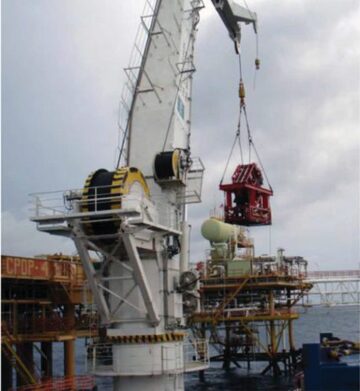
Knuckle-Boom Crane. This type of crane was used for lifting the CT equipment required on the platform for full-catenary operations (Fig. 1).
Auto-Compensated Gangway. This system was a vessel-based, self-stabilizing platform that actively compensated for all vessel motion to provide safe offshore access to the platforms. The system helped reduce gangway rig-up time, eliminate potential hazards from transfer by boat, and reduce operating downtime caused by environmental conditions.
The auto-compensated-gangway platform actively compensated wave-induced motions of the vessel in six degrees of freedom by individually actuating each of its six hydraulic cylinders. Also, a flexible telescoping access bridge (gangway) was installed on top of the auto-compensated gangway platform to passively compensate for any remaining motion and extend the gangway to the landing position.
To transfer personnel, the gangway was lowered to the vessel deck, and personnel were transferred to the gangway platform. The operator then adjusted the gangway platform to the required height and pitch and extended the telescoping gangway to the landing area. The end of the telescoping gangway maintained a contact force on the landing structure at all times. The gangway operator then signaled that it was safe for an individual to cross the gangway. Once all personnel were transferred, the telescoping gangway was retracted and stowed on the vessel.
Emergency evacuation drills, including stretcher cases, were performed and included in the vessel’s emergency-response plans.
CT and Pumping Unit With Full-Catenary System. The stimulation vessel was originally designed to minimize the quantity of CT equipment transferred onto the production platforms, allowing work to be performed on smaller platforms with limited deck space, reducing rig-up time and lifting hazards, and avoiding overloading of the platform structure. An added safety benefit was that, because no engine-operated equipment was placed on the platform, a potential ignition source was eliminated.
CT, Nitrogen, and Pumping Equipment. A complete set of CT, nitrogen, pumping, and acid-blending equipment was installed on the vessel to provide all CT with well-intervention capabilities. To further reduce the number of lifts to the platforms, a redesigned lifting frame was built that allowed the injector and injector-jacking frame to be lifted as one unit. The single-lift design saves vessel deck space. A subbase with International Organization for Standardization (ISO) locks was added to the injector-jacking frame to secure it to the vessel during transport. The subbase ISO locks were also the attachment points for the casters used for positioning the injector once on the platform. A support was designed to be positioned between the injector frame and injector-jacking frame to alleviate some of the weight from the injector while in transport mode. The lifting frame was removed once the injector was on the platform.
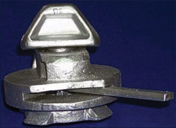
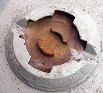
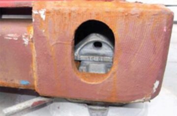
Equipment Sea Fastening. On the stimulation vessel, ISO locks were used to secure all equipment to the vessel deck instead of using traditional methods such as chain and boomers or welding equipment. Because some of the equipment had the same footprint area, using ISO locks provided more flexibility with respect to equipment placement and changeout in the event that repairs were required. The empty raw-acid tanks and liquid-nitrogen tanks were easily replaced with full tanks between jobs using this system. Most of the equipment used on the vessel had built-in ISO blocks. For equipment without built-in ISO locks, subframes were added. The ISO lock system consisted of the ISO blocks, lock, and lower mounting section. The ISO locks worked by installing the lock into the lower mounting section welded to the deck. Next, the equipment with ISO blocks was positioned onto the lock, and the lever was turned, locking the equipment to the deck. The lower-mounting-section ISO-lock welds were all magnetic-particle inspected before operation of the stimulation vessel. ISO locks have long been used in the shipping-container industry and provide a safe and secure method of attaching equipment (Figs. 2 through 4).
The ISO blocks provided an additional benefit as an attachment point for hydraulic-lift casters when moving the lifting frame onto the platform deck. Once the casters were installed, a hydraulic hand pump was used to raise the injector--jacking frame off the deck, allowing easier movement.
Full-Catenary System. The system was designed so that the CT power pack, control cabin, and pumping and mixing equipment remained on the vessel. Only the CT injector, tubing guide, and pressure-control equipment were lifted to the platform. Additional flowback equipment could be positioned on the platform, depending on the job requirements. Two video cameras were installed on the platform. The display monitor located in the control cabin allowed the CT operator to observe what occurred on the platform at all times. An emergency-disconnect system also existed that could be activated if the vessel needed to pull away from the platform during an emergency.
All hoses from the platform were equipped with recovery slings, which allowed quick retrieval so that operation could be resumed in a short time period. A Koomey unit was also placed onto the platform to operate the safety blowout preventer (BOP) in the event that an emergency disconnect from the platform was required.
Well Control. Once the CT was cut at the reel and the vessel pulled away, well control was maintained by means of external barriers, the BOP and Koomey system, internal barriers, and the double-flapper check valves in the CT string. Once the conditions allowed the resumption of CT and stimulation activities, the CT could be rejoined by use of double-ended connectors. All hydraulic hoses could be retrieved and reconnected for operations.
Job Results
Throughout the 4 months that the vessel was used in the field, 28 acid-stimulation and well-intervention operations were performed with a 100% operational success rate. The high-priority work on the injection wells helped achieve greater injectivity than the operator expected. The operator has applied the lessons learned using the enhanced concepts trialed during this work period to a new intervention vessel.
This article, written by JPT Technology Editor Chris Carpenter, contains highlights of paper OTC 24693, “Enhancing the Operational Envelope for Offshore Coiled-Tubing Interventions To Be Performed in Monsoon Season,” by Reawat Wattanasuwankorn, Franklin Hammer, and Richard Christieson, Halliburton—Boots & Coots, and Yan Song and Nick Long, Brunei Shell Petroleum Company, prepared for the 2014 Offshore Technology Conference Asia, Kuala Lumpur, 25–28 March. The paper has not been peer reviewed. Copyright 2014 Offshore Technology Conference. Reproduced by permission.