The Nini East field represents a significant drilling challenge. The target is a post-depositionally remobilized sand reservoir with a thickness of 2‒15 m. None of the standard well-placement methods or current mapping tools was a suitable solution for the well objectives. A field test of the next-generation bed-boundary mapping tool was launched to geosteer two upcoming production wells. The two producers achieved an outstanding 0.99 and 0.96 net pay ratio with no sidetracks or delays and were completed within budget.
Introduction
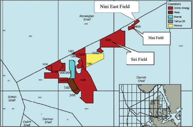
The Nini East field is located 3 km south of the border between the Danish and Norwegian sectors of the North Sea (Fig. 1) and was discovered in 2001, when oil was found in the Kolga-member sandstones of the Upper Paleocene/Lower Eocene Sele formation.

The challenges in drilling horizontal wells in this type of reservoir include a complex geological setting—leading, in some wells, to a low net-pay ratio—combined with the unstable reservoir-capping Sele shale, which increases the risk of having to drill sidetracks.
The Kolga-member reservoir of the Nini East field consists of a glauconite-rich sandstone with unique characteristics. Although initially deposited as traditional gravity-flow sands, the Kolga sands have been remobilized under burial, leading to sand fluidization and injection along weakness zones. These traits create difficulty in defining the exact stratigraphic location of the sand.
With these challenges in mind, the Dansk Olie og Naturgas company (DONG E&P) launched the development of the Nini East field in 2009 with a drilling campaign including two horizontal producers and one injector in the Kolga sand. The two main goals were to increase the percentage of horizontal section in pay while avoiding the Sele shale and maintaining the oil/water-contact (OWC) standoff.
Methodology
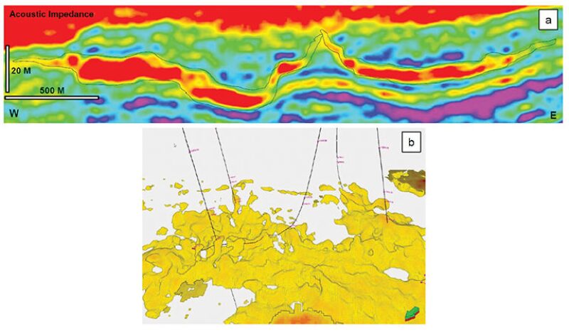
The operator decided that much-needed uncertainty reduction could only come from significant investment in seismic-data processing and inversion, combined with the new-generation deep-directional-electromagnetic (DDE) service-placement workflow. The seismic data were reprocessed and inverted to improve the imaging of the injectite sands. The seismic resolution was improved from approximately 10 m on the conventional seismic data to approximately 5 m on the inverted cube (Fig. 2).

The primary method of trajectory adjustment involves correlating the logging-while-drilling (LWD) log response acquired on a drilling well with offset data acquired along previously drilled wells in the area. This implicitly relies on the assumption that the formation is continuous between the offset wells and the current drilling location—an assumption that may not hold in faulted reservoirs, pinchouts, unconformities, or highly remobilized reservoirs such as those found in the Nini East field.
The second traditional method, borehole-image analysis, is normally used to assess and control the relative dip and azimuth between the well being drilled and the formation bedding. The limitation for that method is that the structure identified on the images is representative of the overall geometry of the reservoir. Because of the remobilized nature of the reservoir in Nini East, borehole images will not provide the necessary information for effective well placement.
The third, and more recent, method is the use of commercially available real-time bed-boundary mapping services based on electromagnetic measurements with azimuthal sensitivity. This service, often referred to as deep-directional resistivity LWD, is capable of imaging resistivity boundaries up to 5 m away from the wellbore in good resistivity-contrast cases with relatively favorable geometries.
In Nini East, the resistivity of the reservoir is lowered to less than 5 Ω⋅m. As predicted by the physics of electromagnetic signals, simulations performed before drilling indicated that the poor resistivity contrast between the low-resistivity pay and the shale would reduce the depth of investigation (DOI) of the directional resistivity tool to less than 2 m. Given the reservoir thickness of up to 15 m, this DOI would not be sufficient to manage the changes in reservoir dip seen on the seismic data.
Using the New-Generation DDE Service To Image the Reservoir in Real Time. The DDE service consists of a new LWD tool and a new processing method. It was designed to address the widest envelope of scenarios, from real-time deep-reservoir imaging and steering to complex, finer-scale geosteering such as that required in Nini East. The nominal radial DOI has been proved to reach 30 m around the wellbore, more than six times the previously available DOI for deep-directional-resistivity services.
Several beds can intersect the 60-m-wide visibility window centered at the wellbore. The processing method was built to image complex formations with multiple beds and take advantage of the rich information content of the new tool measurements, in terms of both resolution and coverage of the volume of investigation. The real-time inversion result is a resistivity cross section of the reservoir shown on a canvas of true vertical depth (TVD) vs. true horizontal length along the well trajectory used for real-time steering decision making.
The DOI of the new-generation DDE tool is comparable with the resolution of the seismic data in this example. Thus, the DDE inversion results and the seismic interpretation can be overlayed in real time to combine the interpretations and increase the understanding of the reservoir geometry while drilling.
Results
To maximize the net-pay ratio within the Kolga reservoir, DONG E&P decided to use a bottomhole assembly that consisted of the new-generation DDE tool and a multifunction formation-evaluation LWD tool with propagation resistivity, gamma ray, density, porosity, and resistivity measurements. In addition, the commercially available deep-directional-resistivity tool, which also has a propagation-resistivity array, was part of the assembly. The steering tool was a point-the-bit rotary-steerable system, critical in achieving the fast trajectory updates required by the geometry of the reservoir.
To ensure the success of this drilling campaign, the DDE inversions, surface seismic data, and LWD logs were combined so that steering decisions could be made ahead of the changes in reservoir structure, thereby enabling the well to be placed high within the reservoir but away from the unstable shale all the way to total depth.
First Well: NB-1. The planned NB-1 well had a horizontal section of 750 m and a hole size of 8.5×9.5 in. The structure along the NB-1 well was complex, but the top of the reservoir was clearly imaged, and lateral changes in resistivity were identified as well as most of the base of the reservoir, where the resistivity contrast was expected to be nearly nonexistent.
While drilling these wells, the resistivity boundaries mapped by the DDE inversion were interpreted and displayed in the 3D view along with the seismic data. The boundaries mapped by the DDE inversion were interpreted in real time and seamlessly displayed along the 3D-seismic section. This enabled real-time comparison of the seismic data with the DDE inversion.
Surface seismic data usually have lateral and vertical uncertainties of several meters to tens of meters when converted from time to depth, which makes the seismic data less reliable for steering in thin reservoirs but provides very useful information away from the borehole. The seismic uncertainty is addressed by steering the well relative to observations made on LWD logs and real-time inversions derived from LWD measurements. Two main benefits of all LWD measurements are the very high depth accuracy with respect to the wellbore trajectory itself and the high resolution (from a couple of centimeters to a few meters). For these reasons, surface-seismic and LWD DDE inversions complement each other in a natural way in scale, precision, and accuracy.
The first steering decision based on the seismic data was made immediately after the tie was validated, near 3000‑m measured depth (MD). Because the reservoir’s roof was deeper than initially expected, the team decided to lower the next drilling target by 1 m in TVD. This decision ensured a safer distance from the top reservoir in advance of the newly anticipated downward dip change in that surface.
Even if the well trajectory had stayed within the reservoir, it would have been within a short distance of the roof, at the mercy of any rugosity of this reworked reservoir, bringing the operational risk to an unwanted level. During the remainder of the operation, the well trajectory was updated numerous times on the basis of the combination of the DDE inversion and the surface seismic data.
The NB-1 well was drilled in a single run, achieving a horizontal section of 815-m MD with a net/gross ratio of 0.98. Overall, the planned 750 m in reservoir exposure was exceeded by 65 m. The risk was managed in such a way that the steering options remained flexible for as much of the well as possible to cope with the unexpected nature of the Kolga-sand geometry. The tortuosity of the well was kept within requirements with an average rate of penetration above 30 m/h, almost twice as fast as what is considered standard in Nini East.
Second Well: NB-2. The planned NB-2 horizontal well had a short reservoir section of 260 m and an 8-in. hole size. The reason behind such a short reservoir section lies in the production strategy; drilling the well further would bring it directly above the OWC, resulting in earlier water production. Therefore, one objective of this job was to stop drilling when the team saw a significant drop in the base reservoir (dipping into the water zone).
From the start of the drilling of NB-2, the DDE inversion provided resistivity boundaries in real time at a distance of 7-m TVD from the wellbore. Because the reservoir does not exceed 10 m in thickness, the well was placed in the reservoir throughout the section, while the maximum detection range for the new tool was not actually reached.
In this second well, the resistivity in the target turned out to be slightly higher than expected, leading to a sharper DDE inversion of the reservoir boundaries more in line with that observed in standard scenarios. This time, both the top and bottom boundaries were well-defined throughout the section.
The steering was performed confidently, managing expected changes in the surface above and below ahead of time. The final part of the well, after 2750-m MD, shows the bottom of the reservoir quickly moving out of sight, as expected. The ability to see this event clearly on the real-time DDE inversion led to the decision to stop drilling immediately. The NB-2 well was drilled in one run, achieving 260-m MD in the Kolga sand with a net/gross ratio of 0.96.
This article, written by JPT Technology Editor Chris Carpenter, contains highlights of paper SPE 159132, “Geosteering the Impossible Well: A Success Story From the North Sea,” by Soazig Leveque and Christophe Dupuis, Schlumberger; Thomas Stærmose, Estela Vazquez Esmerode, and Peter Sommer Linnet, DONG E&P; and Graham Raeper, Schlumberger, prepared for the 2012 SPE Annual Technical Conference and Exhibition, San Antonio, Texas, USA, 8–10 October. The paper has not been peer reviewed.
