High-reliability gas lift flow-control devices (GLFCDs) enable gas lift for wells with the potential for H2S in the produced gas and where casing is not qualified for H2S service. Valve specifications are such that no leakage is allowed at both high (8,000-psi) and low (1-psi) differential pressures across the valve. A series of tests was designed using the environmental-stress-screen (ESS) concept and a harsh test standard that greatly exceeds API specifications for GLFCDs.
Introduction
GLFCDs are usually incorporated into the production conduit and used to inject high-pressure natural gas from the injection conduit to the interior of the production conduit. Commercially available GLFCDs typically contain one-way check systems comprising a ball, hemisphere, or cone, which is pressed against a valve-seating ring by a spring. Unfortunately, many GLFCDs are prone to wear and damage because of fluid cut during the operation.
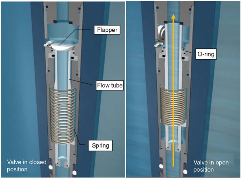
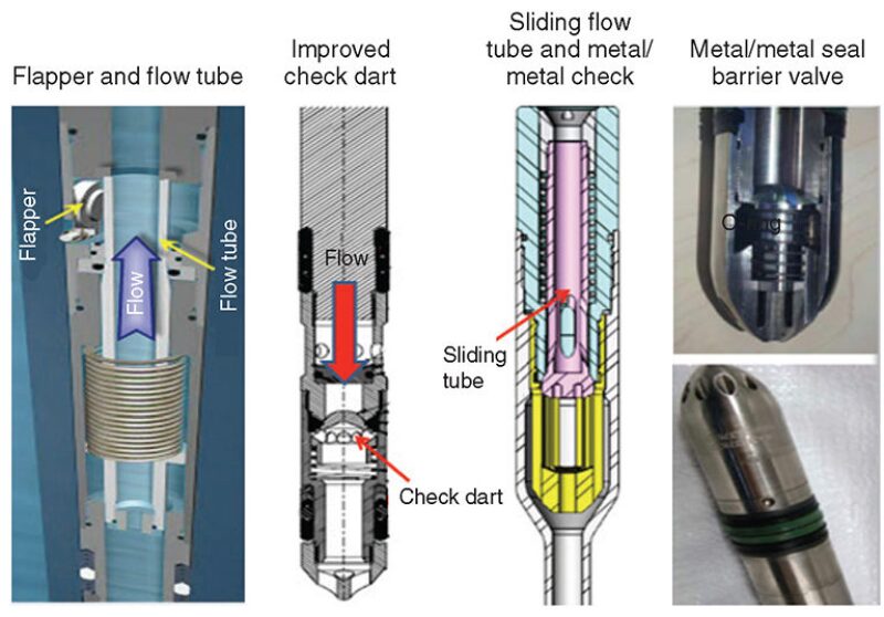
Some of Shell’s Gulf of Mexico deepwater wells commonly produce sour fluids, which the casing program was not designed to tolerate. When sour production enters casing that is not qualified to National Association of Corrosion Engineers standards, the wells cannot be produced. Therefore, a family of high-reliability GLFCDs has been developed for use in deepwater/subsea associations. This technology is viable for any gas lift well because of significant cost savings in change-out of GLFCDs and the ability to maintain well integrity. Fig. 1 presents schematics of the GLFCD through which liquids are unloaded from the casing annulus into the tubing, while Fig. 2 details several types of high-reliability GLFCDs.


High-Reliability-GLFCD Design Validation and Qualification Procedures
A series of design validation and qualification tests has been established and executed to determine whether high-reliability GLFCDs meet the acceptance criteria of API or ISO standards and Shell specifications and qualifications. Shell’s test program for these GLFCDs comprises three parts: factory acceptance, qualification, and endurance. Every individual GLFCD that has passed all factory-acceptance tests would be deemed accepted for installation and service. If the prototype of a GLFCD has passed Shell tests, it is deemed qualified to be a high-reliability GLFCD. Currently, three gas lift manufacturers have developed GLFCDs and products that have been tested using Shell’s test program; these test results are described in the following sections.
Erosion Tests With Fresh Water
The purpose of the erosion test is to evaluate erosion-resistance performance and reverse-flow-check capacity of the GLFCD. In this test, city water will be pumped through the fixture and the test sample at 1 bbl/min until the total flow volume reaches 4,000 bbl or the test sample fails a periodic reverse-flow test. When the accumulated flow volume reaches 400, 2,000, and 4,000 bbl, the flow test is paused and the reverse-flow leakage is performed with nitrogen or air at five differential pressures from the normally downstream side of the valve: 1, 5, 50, 100, or 1,000 psig. If the measured leakage rate is 0 cm3/min at differential pressures at these values after flowing a total volume of 4,000 bbl, the valve passes the erosion test. If it fails, the test sample will be disassembled and the internals photographed for the root-cause-of-failure analysis. The comparison of the tests demonstrated that high-reliability GLFCDs dramatically outperform standard ones in terms of reliability and performance.
Endurance Tests
Test of High-Reliability GLFCD: Valve A. The flow loop has a 2-in. line tied into a 2-in. natural-gas line that comes into the facility at approximately 40 psi. Once the system is full, the supply line is closed and booster pumps/compressors are used to increase the available test pressure to approximately 1,200 psi in the loop. Two high-reliability GLFCDs using flapper and flow-tube technology were installed in parallel, and one orifice valve was installed into the pocket of the test fixture. The system was then flowed for approximately 1.5 hours for the temperature to reach a desired 80–85°F.
When the chatter test started, the flow rate through the devices was dropped incrementally to .01 MMcf/D from the initial highest flow rate, and no chatter was heard by ear or stethoscope. The second trial was made by increasing pressure incrementally to 2.38 MMcf/D; here, too, no chatter was heard.
The cycling test consisted of raising the flow rate by fully opening the downstream valve. The cycles were controlled by an electronically controlled motor valve. Each cycle took approximately 3 minutes until 1,000 cycles had been reached. The test took approximately 50 hours total. The valve did not leak within a wide range of pressures. The 24-hour continuous test began immediately after the cycle test. The upstream pressure was held at approximately 1,100 psi, with a downstream pressure of approximately 960 psi, for a differential of approximately 150 psi at a rate of approximately 2.4 MMcf/D. After the GLFCDs were returned to the manufacturer, they were disassembled and no damage was found.
Test of GLFCD: Valve B. First, gas flowed through the valve until a metallic chattering noise was heard, at which point the flow rate for chattering was determined. Next, in the cycling test, gas flow was gradually increased from zero to the maximum flow rate (approximately 2.7 MMscf/D). The flow was kept stable for 1 minute before shut-in and valve closure. This cycle was repeated 1,000 times, and the valve was removed from the test fixture for leak testing, although results were unable to determine whether the valve passed the leakage test. The Shell requirement of zero bubbles over a 3-minute period was met at all pressures after the valve had been set with 2,000 psi.
Test of Improved Check-Dart GLFCD: Valve C. The last devices tested were GLFCDs with two external check valves and one orifice valve with check darts and seal rings as a primary reverse-flow-check system. The GLFCD passed the initial leak test per the Shell qualification of zero bubbles. After the chatter test, all the devices had no visible damage to any valve component.
Barite-Endurance Tests
The purpose of barite-endurance tests is to determine whether the gas lift barrier valve can meet Shell high-reliability-GLFCD qualification requirements of the bubble-tight leak criterion after a mixture of barite and water has been circulated through it. The downstream pressure, the mixture density, and the mixture flow rate are kept constant, while the upstream pressure varies freely. Once the test is concluded, the gas lift barrier valve is retrieved from the loop, cleaned, and installed in a leakage-test facility for conducting the reverse-flow test.
Barite Test: Modified Valve A. Valve A was modified with the installation of a tungsten carbide check dart for the barite test. On the basis of the new test protocol, this valve was tested for 9.38 hours over 2 days (the test was stopped during the night shift) until completing a total volume of 1,151 bbl. The flow rate was kept constant at 2.04±0.033 bbl/min for an equivalent density of 10.06±0.028 lbm/gal. The modified valve was retrieved from the facility after completing 1,153 bbl. No substantial deposit of dried barite was found in the valve or the check dart. Because no sign of erosion was observed in the check dart and seals, the valve was reassembled and installed in the reverse-flow-test facility. The gas-leak test was carried out at 1, 15, 50, 500, 1,000, and 1,900 psig, with no gas leakage at any of those pressures. After the test, the modified Valve A was then retrieved from the flow loop and cleaned to remove barite residue. No significant erosion damage was observed in the valve inlet port. Some dried barite was found in the valve, which was flushed as part of the cleaning process.
A preliminary gas-leak test was performed at 1,900 psig. Excessive gas flow was then observed, which was higher than the maximum that can be measured by the water-displacement method. Similar results were obtained at other pressures. On the basis of this result, the modified Valve A did not meet API 19G2 or Shell high-reliability-GLFCD specifications.
Barite Test at 10 lbm/gal: Modified Valve B. This test was conducted until a total of 2,050 bbl of barite mixture had been flowed in 20.82 hours. The mixture density was kept at 10.02 lbm/gal, varying within a range of ±0.054 lbm/gal. Although the flow rate was kept constant during the test, it varied between days, ranging from 1.55 to 1.69 bbl/min. There was no visible structural damage on the valve body.
The manufacturer ran a gas-leakage test on the valve after the flow test. The valve stayed sealed at 5, 100, 500, and 1,000 psig. This result shows that the valve passed the barite test at 10 lbm/gal. The manufacturer noticed severe erosion around the inlet port; however, it was concluded that the check system was still functioning. During the valve disassembly, the manufacturer found that large amounts of barite had accumulated around the tube and spring housing. The manufacturer found that the valve flapper and flapper spring did not show any sign of erosion damage. The valve teardown also revealed that neither the seat O‑rings nor the seat was damaged during the test.
Barite Test at 10 lbm/gal: Modified Valve C. The barite mixture was flowed through Valve C until completing 2,110 bbl of accumulated total volume. The pressure drop across the valve and the flow rate varied across the days. The manufacturer conducted a visual inspection of the valve, reporting moderate erosion on the valve exterior side of the inlet port. The damage was on one exterior side of the valve port between the packing stacks, and was associated with erosion caused by barite abrasion. The valve leaked during the leakage test, and was then dismantled for further inspection. The valve teardown revealed no significant damage in the valve-check system. The gas leakage was then attributed to barite deposits that caused the check dart to stick in an off-seat position. Therefore, the valve was reassembled using the same components. The valve was then tested at 100, 500, 1,000, and 2,000 psig. No gas leakage was observed at any of those pressures, and therefore the valve was proved to meet Shell specifications.
This article, written by JPT Technology Editor Chris Carpenter, contains highlights of paper SPE 159848, “High-Reliability Gas Lift Flow-Control-Device Technology and Erosion/Endurance Tests,” by Jun Xu, Stuart L. Scott, SPE, and Wayne Mabry, SPE, Shell E&P, and Jose Gamboa, SPE, The University of Tulsa, prepared for the 2012 SPE Annual Technical Conference and Exhibition, San Antonio, Texas, USA, 8–10 October. The paper has not been peer reviewed.
