

This paper will demonstrate the benefit of liner-drilling technology used to drill and cement an operator’s 9⅝- and 7-in. liners in place, allowing for the continued development of oil reserves in the Carpa and Bagre fields of the Faja de Oro area offshore Veracruz, Mexico. Before the introduction of drilling-with-liner (DWL) technology, two previous wells drilled in the Carpa field encountered massive lost circulation and hole instability while drilling into the El Abra limestone, resulting in a total of 55 days of nonproductive time (NPT) for the two wells.
Introduction
Nine fields have been developed in the offshore Faja de Oro area of the Gulf of Mexico (Fig. 1). They are the Arrecife Medio, Isla de Lobos, Tiburon, Bagre, Atun, Morsa, Escualo, Marsopa, and Carpa fields, and to date the estimated cumulative production is some 210 million BOE of light crude ranging from 30 to 40°API from the El Abra Middle Cretaceous limestone.
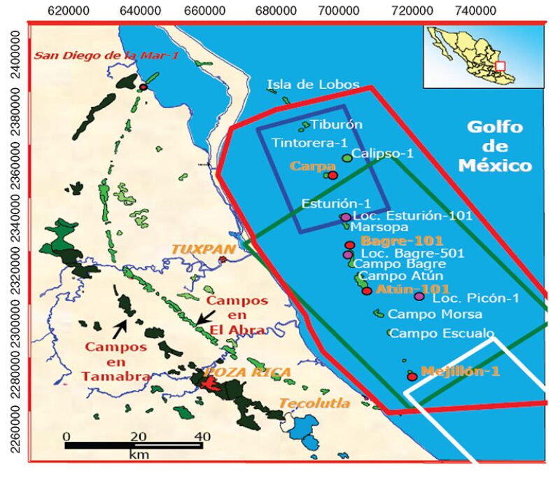
The Carpa field is located in approximately 160 ft of water. Geologically, it is located on the eastern flank of the Tuxpan Cretaceous shelf feature, and the project lies between the prominent structural erosional crests. The sedimentary column that a well will encounter includes the largely clastic recent beds and Tertiary beds above the producing zone. The El Abra reservoir rock consists of back-reef, fossiliferous (milliolid) lime packstone and grainstone, which are the producing zones in the Faja de Oro area, and the reservoir seal above the El Abra producing zones consists of impervious Miocene (Tertiary) shales. The El Abra formation was eroded extensively before Miocene burial, which has resulted in a complex paleosurface of almost random highs and lows. As a result of this erosional history, the structural depth of the El Abra is quite difficult to predict and, furthermore, the differential pressure between the overlying Tertiary shales and the El Abra zone has resulted in several serious downhole problems, including severe lost circulation, stuck pipe, cave-ins, and poor cement jobs (for a discussion of the difficulties experienced with wells in the Faja de Oro region, please see the complete paper).
The reservoir occurs at depths of approximately 7,497 and 8,557 ft for the Carpa and Bagre fields, respectively, with a net thickness of 131 to 348 ft. Porosity averages 18%, and permeability ranges from 7 to 3,000 md. The El Abra is associated with a very strong waterdrive, and data from the other wells of the field indicate that decline has not yet occurred.
Evaluation of DWL Technology
With knowledge of the lost-circulation issues in the naturally fractured portion of the El Abra limestone and also in shale zones, the operator began to investigate alternative solutions to fulfill the following objectives:
- Ensure that the drilling liner can be set at its planned depth into the top of the El Abra formation.
- Provide an efficient method of isolating the Tertiary Brecha shale while landing the drilling liner in the top of the El Abra in a single hole section.
- Provide for a competent cement job, eliminating the requirement for remedial cementing.
- Minimize or eliminate NPT for the operation.
The operator determined that the use of DWL technology offered the best chance of achieving these goals. As a result, it was planned to drill the section into the top of the El Abra formation in two stages, first using a conventional directional-drilling system with continuous rotation to build a high-angle hole, and then, after reaching a suitable depth determined by the on-site geologist, switching to the DWL method and drilling to the top of the El Abra, maintaining the same high-angle hole and immediately hanging the liner and cementing it in place, thus optimizing its set point.
Equipment Selection
Because of the demanding nature of the proposed DWL operation with the extremes of loads and torques to which the liner and the liner-hanging equipment would be exposed on a long-term basis, the choice of equipment was critical to the success of the project.
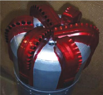
Casing-While-Drilling (CWD) Drill Bit. After review of bit performance in the original wellbore, the 9⅝×12¼-in. and the 7×8½-in. displaceable CWD bits were selected for the respective 9⅝- and 7-in. DWL operations because the cutting structure was considered the most appropriate to drill the proposed hole interval. The CWD drill bit chosen was a polycrystalline-diamond-compact (PDC) bit (Fig. 2) with features that enabled it to be converted to a drillable casing shoe at total depth to enable shoe-track drillout with conventional drill bits (either PDC or roller-cone bits). The cutting structure is designed for formations with unconfined compressive strengths up to 15,000 psi and has 13-mm PDC cutters and tungsten carbide gauge protection. The gauge-section design enables back-reaming capability, and the CWD bit can be fitted with drillable copper or ceramic nozzles instead of carbide nozzles, which can severely damage the bit used in the subsequent drilling out of the shoe track.
Liner-Hanger System. The liner-hanger system (Fig. 3) used for these demanding installations has to be able to support the same extreme dynamic forces that are encountered by openhole drilling tools while still being able to perform its designated functions at the final installation depth. For a full discussion of the liner-hanger system and the rationale for its use, please see the complete paper.
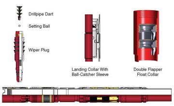
Cementing Equipment. A double-flapper float collar was located a short distance above the CWD bit, which allowed the passage of both the 1¾-in. ball dropped to activate the drillshoe displacement and the 2⅛-in.-outer-diameter liner-setting-tool release ball. This float collar served two purposes: (1) as a mechanical well-control barrier, much like a drillpipe float valve in standard drilling operations, and (2) as a one-way check-valve system to prevent the cement from U-tubing after it has been placed.
Summary of Drilling Operations
Nine wells were drilled with DWL technology in the Faja de Oro area during the period from December 2005 to March 2012, five in the Carpa field and four in the Bagre field. In every case, standard drilling procedures were used to drill to a point defined by the geologist on-site, and then the drillstring was pulled out of the hole (POOH) and drilling continued by use of DWL methods with successful results. A description of operations on four of the five Carpa wells follows (operations on all nine wells are described in the complete paper).
Carpa 3. This first well was drilled in December 2005 with the objective of eliminating a contingency liner above the El Abra formation. Conventional drilling was used to drill a 12¼-in. hole vertically to a depth of 7,808 ft. After conditioning the hole, the drillstring was POOH and a 4,252-ft length of 9⅝‑in., 53.5‑lbm/ft liner equipped with a 12¼‑in. casing bit, cementing float collar, and 9⅝×13⅝‑in. hydraulic liner hanger and compression-set packer was run in on the drillpipe. A further 49 ft of 9⅝‑in. hole was drilled and equipment was rigged up for the cementing process. A 1¾-in. activating ball was dropped and pumped to bottom, and attempts were made to convert the casing bit and activate the liner hanger. These attempts were unsuccessful, and eventually the bottomhole assembly (BHA) was POOH and a full string of 9⅝‑in. casing was run and cemented on the bottom, and the drilling of the El Abra was continued. Examination of the liner-drilling BHA revealed that the flapper in the float collar had sheared off and that the activation ball was jammed in it, thus preventing pressure from building up to convert the casing bit; this discovery led to reconsidering the flapper design. The DWL section of the well encountered no problems, however, and another well was chosen to repeat the process with a revised float collar.
Carpa 55. After a full review of the problems experienced in Carpa 3, some modifications were made to the procedures and equipment configuration, and this well was drilled in May 2006 with similar objectives. A 12¼-in. hole was drilled conventionally to a depth of 9,452 ft at an eventual angle of 75°. The drilling BHA was POOH, and a 4,964-ft length of 9⅝-in., 53.5-lbm/ft liner was picked up and run in the well. It was equipped with a casing bit and hydraulic-liner-hanger system as before, together with a 9⅝×11⅞-in. centralizer placed 72 ft above the casing drill bit and an additional 9⅝×12⅛-in. centralizer placed 72 ft higher in order to help maintain hole angle. A total of 266 ft of new hole was drilled to a depth of 9,718 ft, where the casing bit was converted successfully by use of the 1¾-in. activation ball at a surface pressure of 2,750 psi, which also set and released the liner hanger. This was confirmed by picking up and noting the loss of the liner weight. The liner was then cemented in place, the packer was set by 70,000-lbf setdown weight, excess cement was circulated out from above the packer, and the drillstring was POOH. An 11-lbm/gal oil-based mud was used throughout, and lost circulation and mud loss were negligible.
Carpa 13-H and 21-H. A lengthy hiatus in the Faja de Oro drilling campaign followed until December 2011 and March 2012, when the next two wells in the Carpa field were drilled. In both cases, a 7-in. liner was drilled in and was hung off and cemented successfully and the liner packer was set. The hole angles were in the range of 73 to 75° and were drilled with 11-lbm/gal oil-based mud, with little or no lost circulation being noted.
This article, written by JPT Technology Editor Chris Carpenter, contains highlights of paper SPE 163418, “Use of Liner-Drilling Technology as a Mitigation for Lost Circulation in the Faja de Oro (Golden Lane) Oil Fields Offshore Veracruz, Mexico,” by L.F. Aguilera Naveja, Pemex, and Steven M. Rosenberg, SPE, and Marco A. Dominguez M., SPE, Weatherford, prepared for the 2013 SPE/IADC Drilling Conference and Exhibition, Amsterdam, 5–7 March.