
Solid-expandable tubular (SET) is widely used to patch casing and has proved to be cost effective; however, when the damage is directly below an area previously patched, conventional expandable tubular might not be positioned smoothly because of a loss in wellbore size caused by the previously installed tubular. A new design involves putting the expansion tool outside the tubular. As a result, the expansion ratio could be maximized and the tubular without launcher could pass through the smaller wellbore.
Innovative Structure Design
SET technology is well known for its classic structure (Fig. 1). The expansion tool is put inside the tubular and pushed upward by hydraulic or mechanical means. Usually, rubber is used to seal the annular space between the casing and the tubular. This structure has great advantages in the field and has been used widely across the world; however, one significant weakness cannot be ignored. While the expansion tool is inside the tubular, it restricts the expansion ratio. Therefore, this structure is not appropriate for handling some difficult issues. The most common issue is that the casing often needs to be patched more than once. Usually, the patch position is directly below the previously installed SET, making it almost impossible for the conventional patching tool to be delivered in position. The new design was developed to meet this challenge (Fig. 2).

|
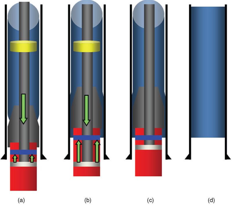
The expansion tool has been placed outside the tubular, powered by a cylinder and piston. An anchor is used to fix the tubular during expansion (Fig. 3). As the SET is delivered into position, liquid is pumped into the tubing to activate the piston. Because of the anchor, the expansion tool can expand the tubular, and the expanded part is stuck to the casing, sealing the annular space (Fig. 3b). After the initial expansion, the tubular is fixed to the casing and the anchor is no longer needed (Fig. 3c). The same process then could be repeated until the end of the expansion process (Fig. 3d).
The advantages of this structure could be summarized as follows:
- Without the restriction of the launcher, the expansion ratio can be increased further.
- The whole set of the patching tool obtained better passing ability.
- The expansion process is more reliable without concerns of breaking the launcher, which was weak because of relatively thin walls.
- The new structure adopted a metal-to-metal sealing method, which is better than rubber in terms of sealing ability and suspending force.
Experimental Test
- A full-scale experiment, consisting of three steps, was conducted to test the reliability and security of the new structure.
- A test of the piston/cylinder system
- An expansion experiment
- A test of the suspending force between the tubular and casing after expansion
The results demonstrated that the powering system was reliable, without any leak under 30-MPa pressure. The expansion experiment was conducted smoothly, with the maximized expansion pressure at less than 15 MPa, and the anchor played its role well. The 8% expansion ratio guaranteed more than 8 t of suspending force between the casing and the tubular given a total contact length of 1 m.
Field Application
Because of the corrosive effect of waterflooding, the casing that had been patched by SET demanded secondary patching. The actual leaking point was only 0.5 m below the previously installed tubular; however, the conventional patching tool could not pass through the bottleneck. Meanwhile, given the short distance between the new leaking point and the previously installed tubular, the new tubular expected to patch the leak point may either fail to cover the right position or overlap the previous one. The newly designed structure, therefore, was considered.
Expansion tools were installed at the upper and lower end of the tubular, with the powering system put between the two. As the liquid pressure intensified inside the piston/cylinder device, the two expansion tools contracted toward each other. The wall thickness of the upper end of the tubular was made exactly half of the rest so that the upper end of the tubular would expand first and the expanded part would not touch the casing yet. Then, the tool set was raised until the expanded part was stopped by the lower end of the tubular installed in the first patching operation. Finally, hydraulic and mechanical means were used to finish the expansion. Afterward, tests proved that the secondary patching operation was a success.
Conclusions
- The new design involved the radical change of putting the expansion tool outside the tubular and, consequently, enhanced the expansion ratio and the passing ability of the patching tool.
- The new technology eliminated the rubber and relied on the contact between the casing and the post-expanded tubular, which was more secure in terms of sealing ability and suspending force.
- All of the laboratory experiments demonstrated the feasibility of the new design in the field. And field tests proved that it can solve some challenging issues that are beyond the capability of the conventional technology.
This article, written by Editorial Manager Adam Wilson, contains highlights of paper IPTC 16429, “Innovative Design of the Solid-Expandable Tubular To Patch the Casing: Area Below the Previously Installed Expandable Tubular,” by Tao Li, Shan Gao, Qiang Chen, Yiliang Li, Weiye Han, Xiuling Bi, and Qiang Sun, PetroChina, prepared for the 2013 International Petroleum Technology Conference, Beijing, 26–28 March. The paper has not been peer reviewed. Copyright 2013 International Petroleum Technology Conference. Reproduced by permission.