This first article in a two-part series discusses a methodology for sizing three-phase separators and quantifying oil/water separation performance in horizontal separators based on estimation of dispersed phase volumes and associated droplet size distributions.
Historically, the sizing of three-phase separators, in particular for oil/water separation, has been based on the specification of residence time criteria. Unfortunately, this is an imprecise method as residence time alone fails to capture many of the parameters/variables that clearly should have an impact on liquid/liquid phase separation performance, e.g. feedpipe conditions, inlet device type, phase flow distribution inside the separator, vessel length/diameter ratio, fluid properties, and dispersed phase droplet sizes As a result, residence time criteria cannot, and do not, reliably correlate to the actual quality of the separated liquid phases such as the amount of water remaining in the oil (WIO) and the amount of oil remaining in the water (OIW).
A somewhat more analytical approach is to size the separator based on specified separable droplet sizes, such as the removal of water droplets larger than 250 microns from the oil phase, or removal of oil droplets 150 microns and larger from the water phase. There are two main issues here:
What is the basis for selection of the separable droplet sizes?
How are the required calculations performed to achieve the target separable droplet sizes? A large number of variables—and assumptions—are involved.
Ideally, the separable droplet size should correspond to a given volume of dispersed phase remaining in the separated continuous phase. For example, the removal of water droplets larger than 250 micron diameter from the oil phase will result in ~3% v/v water remaining in the oil, or removal of oil droplets larger than 150 microns from the water phase will result in ~ 1,000 ppmv oil remaining in the water.
Clearly, the assumption here is that the relationship between droplet size and entrained volume of the dispersed phase is known or can at least be approximated. Are these relationships (one for oil, one for water) fixed? In fact they are not. There are numerous variables involved.
In addition to quantification of the droplet size distribution/dispersed phase (entrainment) volume estimation, utilization of a target separable droplet size requires a number of assumptions to be made in order to perform the actual droplet separation calculations.
This article has two main focuses:
The development of an approximate methodology for estimating the entrained volume vs. droplet size relationships for all three phases
A methodology for performing the actual droplet separation calculations, based on vessel dimensions, internals selection, fluid properties, etc., in order to achieve the specified target outlet fluid qualities
This discussion deals mainly with the oil/water separation aspects of three-phase separator design and operation. A similar approach for gas/liquid separation has been covered in the author’s previous three-part series (Part 1, Part 2, and Part 3).
Feedpipe Conditions
Estimation of dispersed phase droplet sizes and entrained volumes starts with the feedpipe conditions.
There are two main aspects:
Estimation of the three-phase flow pattern in the separator feedpipe. The primary purpose of this step is to estimate the amount of water dispersed as droplets in the oil phase and the amount of oil dispersed as droplets in the water phase.
Estimation of the distribution of the three phases (gas, oil, and water) in the feedpipe, the cross-sectional areas of the feedpipe occupied by each phase (assumes a stratified flow), and the actual velocities of each phase. The primary purpose of this step is to obtain actual velocities for the oil and water phases which will then be used to calculate maximum stable droplet sizes for each of the dispersed phases (water droplets in oil, and oil droplets in water). The calculated maximum droplet sizes are then used to characterize the two droplet size distributions.
In addition, calculations will be performed to determine the effect of any fittings present in the feedpipe, such as elbow, tee, etc., on the feedpipe droplet size distribution.
For the purposes of this analysis, two separate approaches are used for these two steps. This is an approximation that yields what are believed to be reasonable results. Future refinement of this methodology will utilize a single “unified” approach to accomplish the two objectives identified above, similar to that proposed by Zhang and Sarica (2005).
Characterization of the steadiness (or lack of) of the inlet flow is also a key requirement of proper separator sizing but is outside of the scope of this paper.
Estimation of Three-Phase Flow Pattern in the Feedpipe
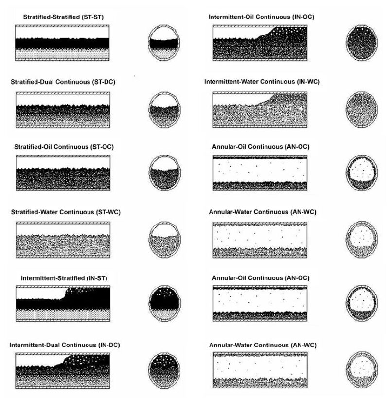
At present, there is very little published information available for estimating the amount of dispersed phase (WIO, OIW) entrained in each of the continuous phases for liquid/liquid flows. The approach utilized in this work is based on the three-phase flow patterns and associated flow pattern maps presented by Keskin et al. (2007), as shown in Fig. 1.
The three-phase flow patterns are described by two-term identifiers, such as ST-DC. ST represents stratified, which describes the gas/liquid flow pattern. DC represents dual continuous, which describes the liquid/liquid flow pattern.
More detailed descriptions of the flow patterns are provided by Keskin et al.
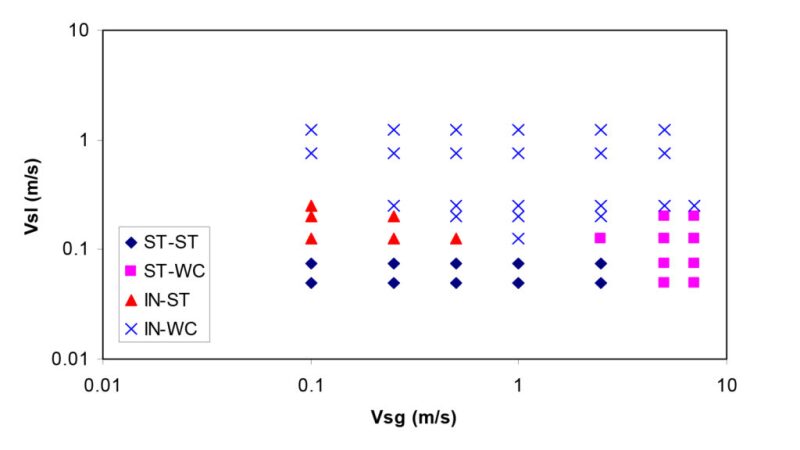
The occurrences of the various flow patterns are shown in associated three-phase flow pattern maps. Keskin et al. provides five flow pattern maps for 20%, 40%, 50%, 60%, and 80% liquid phase water cuts (volume basis). For illustration, the 50% water-cut map is shown in Fig. 2.
Using the flow pattern maps and the descriptions of the flow patterns, estimates can be made of the dispersed phase (WIO and OIW) concentrations for a given set of feedpipe operating conditions. The WIO and OIW concentrations in the feedpipe are also assumed to be representative of the WIO and OIW concentrations at the inlet to the liquid/liquid gravity separation section of the separator, after adjusting for the effect of any fittings in the feedpipe (near the separator inlet) and the separator inlet device. This will be discussed later in this article.
For several of the liquid/liquid flow patterns, it is necessary to define “minimum” or “residual” WIO and OIW levels for use in the subsequent droplet separation calculations. For example, the oil and water phases in stratified liquid/liquid flow are not “pure”—there is some relatively small amount of water dispersed as droplets in the oil and a small amount of oil dispersed as droplets in the water—even though these droplets were difficult to identify and quantify in the Keskin et al. stratified liquid/liquid flow patterns. Similarly for both oil-continuous and water-continuous flow patterns, it is necessary to define minimum concentrations of OIW and WIO, respectively, in order to perform the separation calculations.
The assumed dispersed phase fraction “minimum” levels are shown in Table 1.

Note that these numbers are not predefining the quality of the separate liquid phases. They are only used to provide minimum levels of dispersed phase entrainment at the inlet to the liquid gravity separation section.
For example:
“Average” conditions:
No major shear sources, such as choke or control valve, in the separator feedpipe within a hundred feet upstream of the separator
Medium-light oil (30–40 °API)
Reasonably high-salinity produced water (1.03 < SG < 1.1). Lower-salinity water is more difficult.
Moderately high temperatures (80–120°F). Lower temperatures are more difficult.
No particular/expected emulsion problems
“Easy” and “difficult” conditions can be defined relative to the “average” conditions described above.
Procedure for estimating entrained dispersed volume fractions:
Calculate the in-situ liquid water cut at feedpipe conditions.
Determine the feedpipe three-phase flow pattern from the appropriate water-cut flow pattern map based on 1 and 2 above. Use the water cut map closest to the actual water cut or interpolate between water cut maps.
Determine the WIO and OIW volume fractions based on the identified liquid/liquid flow pattern.
Adjust the “base” feedpipe entrained dispersed phase volumes, if necessary, based on any other shear-inducing elements, such as pipe fittings, that may be present near the separator inlet.
Estimation of the Distribution of the Three Phases
This section discusses the distribution of the gas, oil, and water phases in the feedpipe, the cross-sectional areas of the feedpipe occupied by each phase (assumes stratified flow), and the actual velocities of each phase.
The purpose of this step is to estimate actual phase velocities in the feedpipe, which are then used to calculate dispersed phase droplet sizes. Estimation of gas phase liquid entrainment and droplet size distribution was discussed in the author’s previous articles.
The methodology used is presented in a paper by Taitel et al. (1995). A subsequent paper by Heydari and Sadeghi (2011) provides some additional details that are helpful for performing the calculations (an iterative procedure is required, which can be performed easily by the Solver add-in in Excel). These calculations assume stratified three-phase flow.
While not all feedpipe conditions will necessarily result in stratified three-phase flow, this situation will be quite common and, in fact, generally preferred for three-phase separation applications. In particular, high gas flowrates and correspondingly high gas velocities will result in high liquid velocities, which in turn will lead to smaller dispersed phase droplet sizes which are harder to separate.
Calculation of Droplet Size Distributions for the Liquid Phases
Straight horizontal feedpipe section
The Hinze equation can be used to estimate the maximum dispersed phase droplet size:
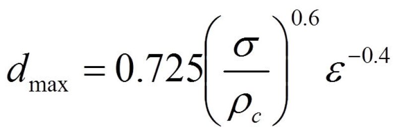
For pipe flow, the turbulent energy dissipation term, ε, can be defined as:
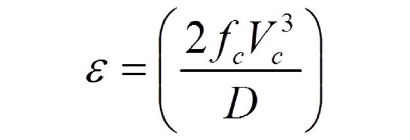
For the purposes of these calculations, the values used for phase friction factor, velocity, and hydraulic diameter are as outlined by Taitel et al. and Heydari and Sadeghi.
Substituting this expression for ε into Eq. 1 gives:
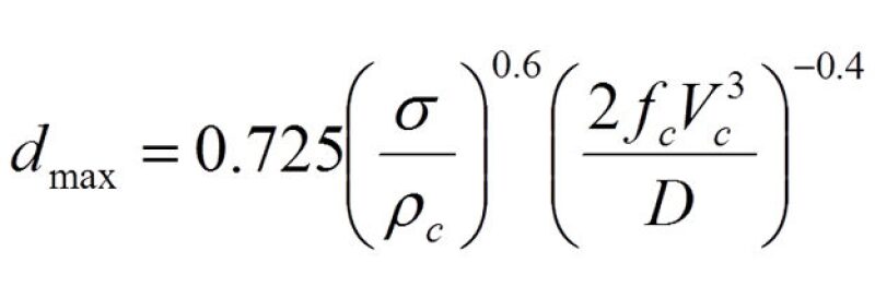
Where:
dmax = maximum droplet size
σ = oil-water interfacial tension
ρc = density of the continuous phase
ε = turbulent energy dissipation rate
fc = Fanning friction factor for the continuous phase
Vc = velocity of the continuous phase
D = effective hydraulic diameter for the continuous phase
Although the Hinze equation is considered to be most suitable for dilute dispersions, say <1–2% dispersed phase by volume, it will be used here for both dilute and dense dispersions. For dense dispersions the maximum droplet size is likely underpredicted by Eq. 3 and therefore is conservative. This form of the Hinze equation also ignores the effect of the dispersed phase viscosity, which may be more significant for OIW calculations involving heavier oil.
For the purposes of this work, Eq. 3 will be applied to both the oil and water phases to get the maximum water droplet size in oil and maximum oil droplet size in water. It should be noted that the calculated dmax values from Eq. 3 are quite sensitive to σ, the value of the oil/water interfacial tension that is used. As the dmax value will impact the dispersed phase droplet size distribution and thus the dispersed volume vs. droplet size relationships for both WIO and OIW, the interfacial tension value selected has a fairly strong impact on the separator sizing calculations.
A future refinement of this model will utilize a correlation for estimating oil/water interfacial tension based on fluid properties and operating conditions such as temperature. Existing oil/water interfacial tension correlations available in the literature are somewhat inconsistent and require additional review. Clearly, if actual oil/water interfacial tension data are available, this is preferable as this parameter is dependent on the oil and water chemistries involved, which makes generalization difficult.
Effect of Fittings in the Feedpipe
It is highly likely that a real-world separator installation will have one or more pipe fittings (e.g., elbow, tee) in the feedpipe relatively close to the separator. These fittings will generate additional shear, may increase entrainment of the dispersed phases, shift droplets to smaller sizes, and will also have an impact on inlet device flow distribution depending on the fitting type and orientation.
Assumptions
Fitting is located at a distance within 15 times the feedpipe diameter from the separator. For fittings located farther away than this, it is assumed that droplets will coalesce and shift the droplet sizes back to the values calculated above for the straight horizontal feedpipe. A linear adjustment factor is used to account for the actual fitting location between 0–15 diameters upstream of the separator inlet.
It is assumed that the number of fittings does not have an effect, only the fitting that produces the highest shear—the “worst-case fitting”—is considered. It is the fitting that generates the maximum value of ε, the turbulent energy dissipation rate. Note that this methodology also shows the extremely negative effect on separation that a choke/throttling valve has on separation performance if located in the feedpipe in proximity to the separator.
Droplet sizes
A modified version of Eq. 3 is used for the worst-case fitting:
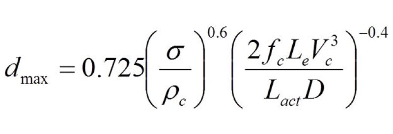
Where:
Le = the equivalent length of the fitting
Lact = the actual flow path length of the fitting
For example, a typical long-radius 90o elbow has an equivalent length of 16 pipe diameters and an actual length of ~2.4 pipe diameters. For a feedpipe internal diameter (ID) of 10 in.:
Le = (10/12)(16) = 13.3 ft
Lact = (10/12)(2.4) = 2.0 ft
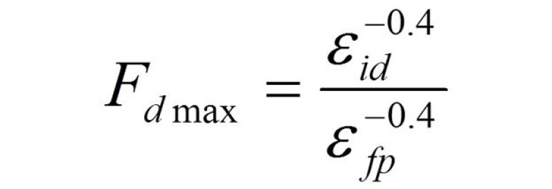
Comparison of Eqs. 3 and 4 shows that a droplet size “shift factor” due to the fitting can be defined as
Increased entrainment of the dispersed phases
The turbulence/shear created by the fitting is likely to cause some fraction of the continuous phases (oil and water) to be entrained into the other liquid phase as droplets, thereby increasing the volume of entrained dispersed phase relative to the “straight pipe” value. This effect is difficult to estimate and is not included in the results presented in this article; it is an area for future investigation.
At this point, the amounts of dispersed WIO and OIW have been estimated as have the maximum droplet sizes for each dispersed phase for the feedpipe, including the effect of any fittings present. The next step is to generate droplet size distributions for each phase. An upper-limit log normal (ULLN) distribution has been used for this purpose as described in Part 1 of the author’s previous gas/liquid separation series.
For feedpipe applications, in addition to the maximum droplet sizes, the parameters used to describe the ULLN distribution are similar to those given by Karabelas (1978) and Simmons et al. (2001) :
a = 1.35
δ = 0.73
These parameters are used for both the WIO and OIW distributions. It should be noted that the separation calculations are quite sensitive to these values.
Flow maldistribution
Various computational fluid dynamics (CFD) studies (e.g., Heijckers 2012), have shown that an elbow in the horizontal plane in the feedpipe within ~15D of the separator inlet can result in a nonuniform flow distribution into, and through, the separator inlet device such that a higher fraction of the flow—in particular, the liquid—is shifted to either the left or right depending on the orientation of the elbow. This in turn will cause increased flow maldistribution in the separator, higher localized velocities, and impaired separation performance in general.
Similar to the fittings’ effect on droplet size and dispersed phase entrainment fraction, the effect on flow maldistribution is adjusted based on the distance of the fitting relative to the separator inlet.
Effect of the Inlet Device
The various types of separator inlet devices and their impact on separation performance in general, and gas/liquid separation in particular, were discussed in some detail in Part 1 of the gas/liquid separation series and will not be repeated here.
With respect to gas/liquid separation performance of the inlet device itself, some improvements have been made to the calculations used:
Several of the inlet devices are characterized by a simple 90-degree change in flow direction (e.g., no inlet device, simple diverter/baffle plate, half-pipe inlet, and the vane-type inlet [with modifications to the calculations]). These inlet devices have been modeled as simple impingement separators where the capture efficiency of entrained droplets in the gas is given by Burkholz (1989) in Eq. 6.
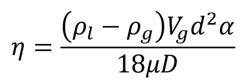
Where:
ρl = liquid density
ρg = gas density
Vg = gas velocity
d = droplet diameter
α = bend angle (radians)
µ = gas viscosity
D = pipe diameter
2. A correlation has been added to estimate the fraction of bulk liquid that is “splattered” into droplet form due to impingement on the perpendicular surface (e.g., diverter/baffle plate), and a correlation for the droplet size distribution of the splattered liquid is also used.
3. For the cyclonic inlet device, approximate correlations for the number of inlet cyclones, the cyclone tube dimensions, and droplet (liquid in gas) removal efficiency have been employed.
As this article is focused on oil/water separation, the above areas will not be discussed further.
While it is possible that several of the inlet device types may cause some degree of oil/water separation, mainly via centrifugal forces and/or coalescence of dispersed phase droplets—in particular, the cyclonic inlet device—there is very little data available to support or quantify these effects. As a result, any oil/water separation and corresponding shift of droplet size distributions that may be attributable to the different inlet devices have been ignored for the purposes of this article. This is an area for future investigation.
In addition to these calculations, a similar methodology to that which was used for a fitting in the feedpipe was also utilized to estimate the effect of the inlet device entrance region on droplet size caused by turbulence/shear. These are only estimates of the expected behavior, but the results look reasonable.
Vessel Sizing
The methodology used for sizing the separator is similar, in most respects, to that presented by Grødal and Realff (1999), and that paper should be referenced for details. However, instead of using predefined separable droplet size targets as the basis for the calculations, the current methodology will utilize the desired outlet fluid quality specifications combined with the estimated inlet droplet size distributions and associated estimated dispersed phase volumes as the basis for the phase separation calculations. A paper by Song et al. 2010 is one of the few other references in the literature that has utilized a somewhat similar approach to the one discussed here.
The calculations required are fairly complicated and iterative in nature because of the various interrelated variables involved. Additionally, for a given separation application there are multiple “technically feasible” solutions possible. As a result, the calculations are performed as an optimization exercise, with the objective function being to minimize total vessel weight—which should correlate to cost—while achieving the specified separation targets and subject to the defined constraints. As for the previously described gas/liquid calculations, an Excel spreadsheet is utilized in conjunction with the Solver add-in.
For a given set of fluid properties, operating conditions, and selected separator internals, the main drivers of the vessel size are as follows:
Separation performance specifications
Amount of water in the separated oil
Amount of oil in the separated water
Amount of liquid in the separated gas
Main constraints
Minimum distance between alarm and shutdown levels
Minimum control band height, i.e., LIL–HIL, LLL–HLL
Minimum times between alarm and shutdown levels
Minimum time for control volume, i.e., LIL–HIL, LLL–HLL
Maximum separator % full, i.e., HHLL/Di
Minimum gas space height
Gas velocity limit to prevent liquid re-entrainment
Oil and water axial velocity limits
Fig. 3 shows the geometry, main components, and level settings for a typical horizontal three-phase separator.
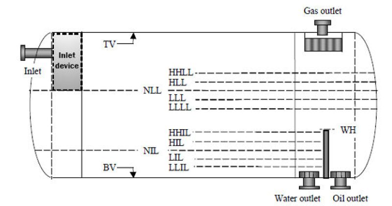
TV–Top of vessel
HHLL–High-high liquid level
HLL–High liquid level
NLL–Normal liquid (oil) level
LLL–Low liquid level
LLLL–Low-low liquid level
WH–Weir height
HHIL–High-high interface level
HIL–High interface level
NIL–Normal interface level
LIL–Low interface level
LLIL–Low-low interface level
BV–Bottom of vessel
Di–Inside diameter
For some applications the minimum distance or times between levels will be controlling, depending on the assumed constraint values selected. Typical values are provided in Table 2.

Clearly, some thought must be given to these values as they can drive the vessel size. The minimum distance requirements can have a major impact on vessel diameter, especially for vessels less than 5 feet in diameter, while the minimum holdup/surge time requirement tend to impact vessel length when using an optimization procedure to minimize vessel weight.
The logic behind the application of these minimum distances/times is often inconsistent. For example:
What are the causes of rising or dropping levels, are they credible, and estimated frequency?
What are the potential consequences of the different rising/dropping levels if left unchecked? Sometimes they are serious, sometimes not.
What intervention options are available to the operator (if there is an operator) when alerted by an alarm, and how long will these take to implement?
It is the author’s view that more attention should be focused on providing adequate “control volume” (the volume between low- and high-level alarms) to handle intermittent/slug flow and smooth out the flows passed downstream. Provision for “operator intervention times” of 2–5 minutes as commonly recommended in typical published separator sizing guidelines is probably not realistic or necessary in most oil and gas applications. Note also that application of the constraints given in Table 2 will often result in a vessel size that is inconsistent with the liquid residence time guidelines recommended by various sources.
For difficult separation applications (e.g., low WIO or OIW specifications, heavy oil [reduced oil/water density difference and high oil viscosity]), separation requirements can sometimes override the above minimum distance/time between levels constraints, though usually increased separation capability is most effectively achieved by increasing the length for a horizontal separator.
Liquid/Liquid Handling/Separation Configuration
For horizontal three-phase separators there are basically four configurations that are typically employed for liquid handling: overflow weir; submerged weir; bucket and weir; and heavy (aqueous) phase boot.
Generally speaking, there are pros and cons to each of these. The boot design would normally only be used for relatively small heavy/aqueous volumes such as <10% of total liquid.
In this article, the submerged weir configuration has been assumed, which in the author’s opinion has advantages over the others from an operability standpoint. The various liquid-handling configurations will be compared in more detail in a future article.
Liquid/Liquid Separation
With respect to liquid/liquid separation, in addition to the actual gravity separation calculations such as Stokes’ Law or Intermediate Law, the following parameters are key:
The droplet size vs. volume relationship for the dispersed phase (WIO, OIW) at the inlet to the gravity separation section
The effective “release point” characteristics of the dispersed phase at the inlet to the gravity separation section
The effective average continuous phase velocity profile along the length of the gravity separation section
Item 1 was addressed earlier in this article. As far as Item 2 is concerned, for both the oil and water phases it has been assumed that the dispersed phase is “released” uniformly across the vertical height of each phase at the vessel centerline at the inlet to the gravity separation section. For the water phase this height is the normal oil/water interface level (NIL) while for the oil phase, the height is taken as the normal oil level (NLL) minus the normal oil/water interface level (NIL). This is less conservative—and more realistic—than the typically employed assumption that the dispersed phase is released as a “point source” at the worst-case release point, i.e., for the oil phase, dispersed WIO is released at the gas/oil contact at the inlet to the effective gravity separation section, while for the water phase, dispersed OIW is released at the bottom of the vessel at the inlet to the effective gravity separation section.
The effective average continuous phase velocity for a given flow rate is a function of several factors:
The axial cross-sectional area occupied by the phase such as oil or water, based on the levels used in Item 2
The inlet device used
The effective gravity separation zone length/diameter
Whether perforated plates/baffles are used for flow-straightening purposes.
The minimum droplet size separated at 100% efficiency is calculated per the settling trajectories shown in Fig. 4.
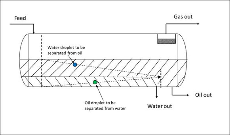
These limiting trajectories are equivalent to equating the vertical settling time to the horizontal transit time for the given dispersed phase, or

Where:
H = height of continuous phase layer (vessel centerline)
Le = effective separation zone length of continuous layer
Vt,100 = settling velocity of the smallest droplet that is 100% removed
Vh = effective horizontal velocity of the continuous phase
Eq. 7 can be rearranged to give the minimum droplet settling/rise velocity corresponding to the limiting trajectory:

This velocity can then be inserted into the appropriate settling law expression (Stokes’, Intermediate) and solved for the minimum separable droplet diameter (100% removal) or D100. For example, Stokes’ Law is shown below:
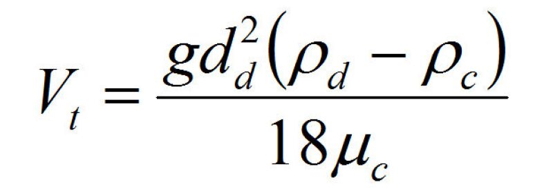
Where:
Vt = droplet terminal settling/rise velocity
g = acceleration due to gravity
dd = droplet diameter
ρd = density of droplet
ρc = density of continuous phase
µc = viscosity of continuous phase
All droplets greater than this size are assumed to be completely removed. Droplets smaller than this size are partially removed.
Given the assumption made in Item 2 above regarding the uniform release of the dispersed phases over the vertical continuous phase height, it can be shown that the removal efficiency for droplets smaller than d100 is given by:
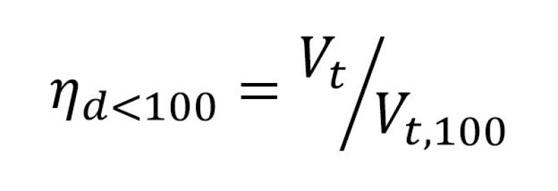
Where:
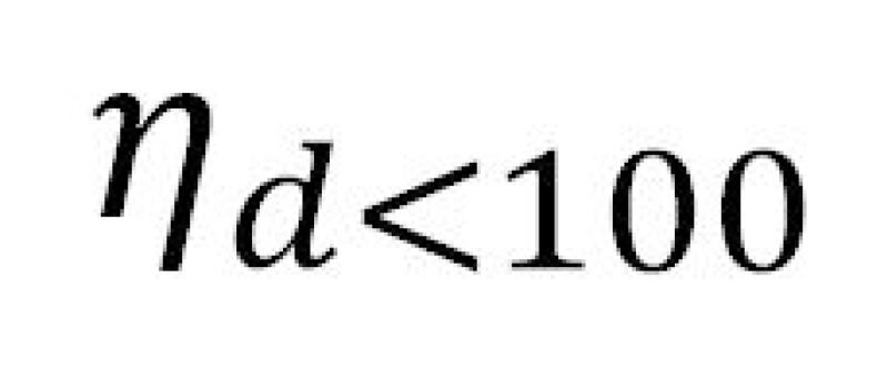
= separation efficiency of droplets smaller than d100
Vt = settling velocity of a given droplet size smaller than d100
Vt,100 = settling velocity of the smallest droplet that is 100% removed
With the d100 values calculated for each phase (WIO, OIW) the removal efficiencies for the smaller droplet sizes can be calculated from Eq. 10. These removal efficiencies are then applied to the droplet size vs. dispersed phase volume relationships (Item 1) for each phase to obtain the overall droplet removal performance. The unremoved (smaller) droplets remain in the separated continuous phases leaving the separator and must be less than or equal to the specified requirement such as WIO <5% v/v, OIW <2,000 ppmv. This “idealized” droplet separation model is modified somewhat by turbulence effects, discussed below.
Effect of Continuous Phase Turbulence on Liquid/Liquid Separation Performance
There are some empirical data available that indicate that the simple vector addition (Vt and Vh) that produces the sloped resultant settling trajectory depicted in Fig. 4 may not be valid for all conditions. The main explanation for this is that turbulence, and the associated vertical velocity fluctuations in the continuous phase, hinders the gravity settling of droplets, especially small ones with low settling velocities.
Operational limits that have been suggested typically take the following form:
Vh/Vt <15, subject to a maximum Vh of 0.05–0.10 ft/sec.
Where Vt is the settling velocity of the target separable droplet size.
The sizing methodology discussed in this article does not use a “target separable droplet size” so the Vh/Vt <15 limit is not applicable.
Both of these constraints can be limiting but the Vh,max = 0.05–0.10 ft/sec limit in particular can be an onerous specification that can drive the separator diameter (axial flow area) upward.
Several of the historical published separator sizing methodologies incorporate these limitations, others do not. The available data to justify these constraints are fairly limited, at least in the public domain, and there is some evidence indicating that these horizontal velocity limits are conservative.
For the current work, axial velocity limits of 0.2 feet/sec are utilized for both liquid phases. These limits should not strictly be necessary if the turbulence effects are quantified correctly. The Vh,max = 0.2 ft/sec limit is typically not constraining for the cases investigated for this article, although occasionally application of this limit to the water phase has required an increase of the oil/water interface level to provide more axial flow area and compensate for curvature of the lower part of the vessel. The effect of turbulence on droplet settling as used here is based on the approach of Miedema and Vlasblom (1996), which deals with sedimentation calculations as used in the dredging industry. While this approach has not typically been applied to oil/water separation, the results look reasonable.
Part 2 of the series presents a base case example with specified parameters to illustrate the methodology and calculations discussed in Part 1.
For Further Reading
Bothamley, M. 2013. “Gas-Liquid Separators—Quantifying Separation Performance Parts 1-3,” SPE Oil and Gas Facilities, August–December.
Zhang, H.-Q., Sarica, C. 2005. “Unified Modeling of Gas/Oil/Water-Pipe Flow – Basic Approaches and Preliminary Validation”, SPE 95749, SPE ATCE, Dallas, 9–12 October.
Keskin, C., Zhang, H.-Q., Sarica, C. 2007. “Identification and Classification of New Three-Phase Gas/Oil/Water Flow Patterns”, SPE 110221, SPE ATCE, Anaheim, California, 11–14 November.
Taitel, Y., Barnea, D., Brill, J.P. 1995. “Stratified Three Phase Flow in Pipes”, International Journal of Multiphase Flow 21 (1), 53–60.
Heydari, N., Sadeghi, M. T. 2011. “Analytical Modeling of Three Phase Stratified Flow in Pipe Using the Mechanistic Method”, CHEMECA 2011, Sydney, Australia, 18-21 September.
Hinze, O.J. 1955. “Fundamentals of the Hydrodynamic Mechanism of Splitting in Dispersion Processes”, AIChE J. 1: 289–295.
Karabelas, A.J. 1978. “Droplet Size Spectra Generated in Turbulent Pipe Flow of Dilute Liquid/Liquid Dispersions”, AIChE J. 24: 170–180.
Simmons, M.J.H., Azzopardi, B.J. 2001. “Drop Size Distributions in Dispersed Liquid-Liquid Pipe Flow”, International Journal of Multiphase Flow 27: 843–859.
Heijckers, C. 2012. “Flow Conditioning Impact on Separations”, SPE webinar, 12 September.
Burkholz, A. 1989. Droplet Separation, VCH Publishing.
Grodal, E.O., Realff, M.J., “Optimal Design of Two- and Three-Phase Separators: A Mathematical Programming Formulation”, SPE 56645, SPE ATCE, Houston, TX, 3-6 October, 1999.
Song, J. H., Jeong, B. E., Kim, H. J. and Gil, S. S., “Three-Phases Separator Sizing Using Drop Size Distribution”, OTC 20558, Offshore Technology Conference, Houston, Texas, 3-6 May 2010.
Miedema, S.A., Vlasblom, W.J. 1996. “Theory for Hopper Sedimentation,” 29th Annual Texas A&M Dredging Seminar, New Orleans, June.

Mark Bothamley is an independent consultant specializing in oil and gas processing and associated facilities and is president of Mark Bothamley Consulting LLC. For the last several years he has been a senior technical advisor for PetroSkills, a large technical training company that supports the oil and gas industry. Previously, he was chief engineer with John M. Campbell and Company in Norman, Oklahoma, for 8 years. Prior to joining JMC he was with BP/Amoco for 24 years, in several locations around the world. His experience covers the areas of design, operation, troubleshooting, and optimization of offshore and onshore oil and gas production and treating facilities. Bothamley is a past chairman of the SPE Facilities Subcommittee and a former member of the GPSA Engineering Data Book Editorial Review Board. He holds a BS in chemical engineering from Lakehead University in Thunder Bay, Ontario, Canada, and a diploma in natural gas and petroleum technology from the British Columbia Institute of Technology in Vancouver, BC, Canada.

