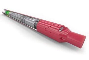
Radio-frequency identification (RFID) offers the user flexibility in controlling downhole operations without intervention. RFID uses close-proximity sensing to communicate by simply passing a coded tag through an antenna-equipped downhole tool to actuate it. Using this technology, an upper-completion system comprising a packer, circulation sleeve, and downhole-barrier valve has been developed that is controlled by a single RFID module, thus providing a means to control the installation remotely, thereby reducing running costs and contributing to the elimination of nonproductive time (NPT).
Introduction
In response to time and cost challenges related to completion in difficult or unstable reservoirs, an enabling technology has been adopted that uses RFID to remotely actuate downhole tools at installation, providing operators with a way to carry out completion operations with a reduced number of employees and without the need for intervention services such as wireline, slickline, and coiled tubing.
The RFID completion system comprises four critical elements: an RFID hydraulic power unit (HPU), a circulation valve, a production packer, and a barrier valve. The system can perform many critical completion operations, including setting packers, opening packer-setting ports, operating sliding sleeves to enable tubing-to-annulus circulation, and closing and opening downhole barrier valves or operating fill subs.
The RFID-based method uses close-proximity sensing to function as the well’s “brain” to control the operation of various downhole devices. Communication is facilitated by running downhole a coded tag that actuates a tool equipped with an antenna. If use of a coded tag is not feasible, the tools can communicate by pressure-pulse signals or timers. The system can test tubing integrity without setting the packer, and it can change out the annular fluid remotely with the packer set and the surface hanger landed. The debris-tolerant design is also insensitive to changes in downhole conditions.
RFID
RFID technology uses radio-frequency communication to identify, track, and operate equipment automatically. Its method of data transfer and its adaptability make it a candidate for widespread application in a downhole environment. It is a close-proximity means of transferring data; no direct line of sight is required, and it works by using two or more devices, principally a reader and a tag. The devices are paired and able to recognize each other through the transmission of radio waves—a tag is coded with relevant information that can be read as it passes an RFID reader. The term “close-proximity” is a relative term. In the airline industry, where readers are able to use vast amounts of power, tags are being read from 100 m; by contrast, in the oil industry this would be reduced to 6 to 12 in., demanding far less power downhole.
The tag, which contains an electronic circuit (transponder), is programmed with specific information. When it approaches the reader, the radio-frequency field generated by the reader powers up the tag, causing it to continuously transmit its data by “pulsing” the radio frequency. The data are then captured by the reader and processed. Some of the other advantages of RFID include the following:
- Tags can be hidden or embedded in nonmetallic materials.
- No line of sight is required.
- It experiences no wear and tear, because of its contactless nature.
- Tags can be read even if covered with dirt or submerged.
- Unalterable permanent serial code prevents tampering.
This technology can be applied to several completion operations, including the following:
- A barrier valve or fall-through flapper valve with bidirectional sealing capability that can be run on the tail of a completion string in the open position and then be closed by RFID for use in setting packers
- A hydraulic circulating sleeve or fracture sleeve that can be opened and closed, either by RFID if pumpdown capability exists or by pressure-pulse technology if it does not
- Remote interval control devices that can be opened individually or in prearranged groups in order to attain the desired production rates from individual formations or sections of the completion
RFID Completion System
Given the obvious advantages that RFID can deliver, a myriad of completion tools could be developed. In one case involving a major operator in the Middle East, in order to ensure alignment with a specific field challenge, a need was identified for a system that would be capable of the following:
- Closing a barrier valve to enable testing of the tubing
- Setting of the production packer
- Opening and closure of the sliding sleeve to enable circulation of the annulus
- Opening of the barrier
All of these tasks had to be performed without any form of intervention.
Having reviewed various design options, the decision was made to develop an RFID “brain.” The brain would be linked up by control line to each companion tool, in this instance a packer, sliding sleeve, and barrier. The rationale behind the design was that the system could become modular, and eventually additional tools could be functioned off a single RFID control module.
The control module provides the hydraulic setting force to actuate or function the companion tools; the module is referred to as an HPU (Fig. 1). The HPU houses the aerial, circuit boards, batteries, pressure gauge, and pump that enable RFID to control the completion system. The HPU is hooked up to companion devices with control lines; up to six different lines can be connected. Depending on the command received, the HPU will direct hydraulic pressure to a specific control line. For example, if the HPU is connected to a packer and a sliding sleeve, there will be a specific command that sets the packer, and specific commands for opening and closing the sleeve.

There are three principal methods of communicating with the HPU—RFID tags, pressure pulses, and a timer—but a mixture of methods is used. RFID tags provide an effective means to convey commands where a circulation path exists. For example, while running in the hole there is a circulation path through the system; once at depth, it is possible to circulate an RFID tag that commands the barrier valve to close. Having closed the barrier valve, the circulation path is no longer present. To communicate with the tool, a pressure pulse can be applied against the barrier, which is detected by the onboard pressure gauge. Depending on the specific sequence of pulses applied, the HPU will direct pressure to the corresponding companion device.
The HPU is self-sufficient in terms of electrical and hydraulic power; there is no reliance on wellbore fluids. The tool has an integral lithium-battery pack that provides the power to illuminate the antenna, circuit board, pump, and pressure gauges. Battery-life capacity far exceeds the requirements of a completion installation, where all activities are performed at the point of deployment. If the HPU is used for other applications, battery life is managed by onboard software that manages power consumption during periods of nonactivity. The HPU has an integral reservoir of clean fluid that is used to actuate companion tools, thus ensuring that debris cannot affect performance. The electrical pump is activated when the HPU is instructed to do so, and a multiposition shuttle valve directs the fluid to the correct tool. The pump is derived from the aeronautical industry, a fact that provides some insight into the reliability requirements demanded of the system.
For a detailed discussion of the production-packer, barrier-valve, and sliding-sleeve components of this application, please see the complete paper.
Qualification Testing
Across the industry, and particularly in the completions sector, there is a quest for new technology, but risk represents a very real barrier to entry. It is commonly noted that there is an overwhelming desire to be the second operator to trial new equipment, not the first.
Testing and contingency planning are the only means of establishing an environment in which new technology can be applied. To this end, a detailed test regime was mandated at component and system levels. Each item was fully tested before system testing. In each case, the relevant International Organization for Standardization standard was the minimum testing criterion applied; in reality, the tests far exceeded the requirements.
In order to validate the system as being fit for purpose and ready for field deployment, a full system-integration test was completed under worst-case well temperatures and pressures, principally 135°C and 5,000 psi (Fig. 2).

The HPU was sent to the field in a dormant state. The tool was switched on and system checked by use of a graphics user interface; this was conducted in the workshop to verify that the HPU was responding and was correctly programmed to recognize the proposed sequence of RFID tags and pressure pulses.
The system was sent to the field in two assemblies and made up on the rig floor. This process was repeated in the workshop to ensure that the procedures as written reflected operational challenges, the main risk being the ability to make up the control-line connections and to test all fittings to verify the integrity of the system. Having simulated the make-up procedures, the system was placed into a test bay where the temperatures were elevated to well-condition levels.
Traditional Approach
When installing a conventional completion, with the exception of hydrostatically set packers, there is always some form of intervention required, whether it be by slickline, electric line, or coiled tubing. Such activities carry with them a risk and time element that becomes increasingly unpalatable to the operator.
If the operation was carried out by use of traditional methods, a number of interventions would be required, including the following:
- Installation of plug body
- Installation of prong
- Trip to open sliding sleeve
- Trip to close sliding sleeve
- Recovery of prong
- Recovery of plug body
Intervention operations are a common source of NPT, whether it be through equipment issues, procedural problems, or various technical errors. Failure to initially test a plug-and-prong assembly can easily amount to 30% NPT. Well debris, operator error, packing damage, damage to nipples, and tool-string selection are the most common contributing factors. Eliminating these activities in terms of tubing testing, packer setting, and fluid circulation realizes not only more than 18 hours of actual time savings, but a full day of time savings when coupled with NPT expectations.
RFID Approach
RFID completion affords the user complete control of the installation without any form of intervention. The other key advantage is flexibility, because the user can tailor the installation to their specific requirements. For example, a single RFID tag can hold multiple commands, whereby the barrier valve, packer, and sleeves can be functioned in a prescribed manner.
Alternatively, the user can function the tools independently. Having all commands run off a single tag does commit the operator to finishing operations within a certain time window; however, this means that users can select the degree of automation that they are comfortable accepting.
For the details of a case study of a remote completion system successfully installed in the Middle East, please see the complete paper. This article, written by JPT Technology Editor Chris Carpenter, contains highlights of paper SPE 166182, “Radio-Frequency Identification Leads the Way in the Quest for Intervention-Free Upper-Completion Installation,” by Iain Adan, Weatherford, prepared for the 2013 SPE Annual Technical Conference and Exhibition, New Orleans, 30 September–2 October. The paper has not been peer reviewed.

