On the basis of a case study in Equatorial Guinea, this paper demonstrates how barrier provisions with remotely controlled open/close technology capabilities enable interventions to be removed from a completion design. The technology described was used in a horizontal subsea producer well drilled to 3460 m. The paper will illustrate how combining downhole electronic control with a full-bore hydraulically operated barrier valve removes any need for running control lines to the surface. Surface-applied pressure and time combinations were used to command remote actuation of the valve.
Introduction
The Ceiba field is located 35 km offshore Equatorial Guinea, west Africa, and is 241 km south of the capital, Malabo. Located in approximately 700 m of water and in one of six subsea clusters in the development, this well was identified as a suitable candidate for inclusion of the technology outlined in this paper.
To maximize reservoir recovery in this field, the completion strategy included a horizontal openhole gravel pack to provide downhole sand control. The completion engineers felt that this strategy would help meet production objectives such as inflow performance. However, it would also require the well to be drilled at a highly deviated trajectory, which would increase the likelihood of the production packer being set at a deviation beyond conventional slickline capability. The remotely controlled downhole valve offered an alternative plugging method to set the packer, test production tubing, and commission subsurface well-control equipment requiring well interventions, and therefore was included for consideration in the well design. The well design would later confirm that the valve would be installed at a deviation greater than 70°.
Plug deployment with wireline and tractor was evaluated in terms of risk and exposure to cost, and from the results of the evaluation, it was concluded that remote technology should be included in the basis of design. A landing-nipple profile located below the packer provided contingency in the event that the remotely controlled valve failed to close.
The final subsea completion design required that the 547-m reservoir section be drilled along a horizontal trajectory, the openhole horizontal gravel-pack system be installed, and the gravel pack be performed. Retrieval of the gravel-pack service tool and wash pipe would mechanically close the fluid-loss control valve to provide isolation from the reservoir during deployment of the upper completion. It would also provide a means of applying the pressure and time signature required to close the barrier valve.
Remotely Controlled Downhole Valve
The self-contained downhole tool combines two main modules to provide a fully integrated computer-controlled ball valve that is opened and closed by remote commands (Fig. 1). The upper module is a downhole hydraulic-power unit that uses onboard electronic control to deliver a hydraulic output. This hydraulic power is used to operate the lower module, a balanced line barrier valve (often known as a lubricator valve). There is no requirement for running control lines to surface.

The valve is preprogrammed at surface at any stage before deployment, and it functions (open or closed) when onboard electronics recognize user-defined commands as being satisfied. The type of command (referred to as a “trigger”) is selected to suit the application and must interface with the overall completion objectives. Command options can be selected to suit each stage of completion deployment.
In the case-history application discussed here, pressure-window commands were used. This option allowed the user to specify pressure and time combinations to instruct the valve to open or close at the correct stages of the completion operation. When applied from surface, any pressure and time combination that falls outside the defined values will be ignored by the device; this feature allows testing up to maximum working pressures without inadvertent actuation of the device.
Well Status Before Upper-Completion Deployment
- Open hole—horizontal gravel pack installed
- Mechanical fluid-loss-control valve closed
- Kill-weight brine with approximate 300-psi overbalance used
- Horizontal tree and blowout preventers installed and tested
- Production casing tested to 4,000 psi
Job Planning and Considerations
The steps taken to plan integration of the new technology within the completion design are outlined in this section. First, the completion design was reviewed and the pressure-window commands were selected. In order to determine job-specific preprogrammed commands (triggers), it is important to identify the functionality required from the technology during the main stages of completion deployment and how other downhole components and operations influence trigger selection.
Run in Hole (Step 1). The valve would be deployed in the open position, which would allow the tubing to self-fill and maintain a circulation flow path so that space out could be verified. It also was important to consider the factors that have the potential to cause inadvertent closure of the valve, including the following.
Circulation of Fluid. Any applied pressure required to circulate a well fluid has potential to be recognized as a command if the rate of increase in pressure is sufficiently fast; therefore, it was agreed that the window should be greater than 500 psi, providing a margin of safety above predicted circulating pressures for this stage of the operation.
Rupture-Disk Burst Pressure. Once the tubing hanger was landed, 700‑psi applied tubing pressure would rupture the disk and establish tubing-to-annulus communication below the packer. Being only 50 psi below the lower end of the proposed pressure window, this risk was managed by limiting the hold period of applied pressure to a maximum of 10 minutes to ensure that the pressure and time combination could not be satisfied.
Running Speed. The device would interpret any rate of pressure change greater than 70 psi/min as a surface-pressure command. Tubular lengths (joints of ±40 ft) and the need to make up each connection meant that this rate of pressure change could not be satisfied; therefore, the running speed was not considered a risk that could enable inadvertent actuation of the valve.
Remote Closing (Step 2). Applied surface pressure against the closed fluid-loss device in the lower-completion assembly would be used to close the barrier valve, with differential pressure limited to 2,500 psi. The pressure-window command needed to be sufficiently low to reduce risk of opening the fluid-loss device, a scenario in which the capability to apply the “close” command would be lost.
Testing (Step 3). Once the valve had been closed remotely, the electronic logic within the tool will consider Trigger 1 as being redundant; therefore, it no longer would require consideration when selecting the next pressure window in sequence, which, in this case, was the opening command. Any operation involving a pressure test had to be considered at this time so that inadvertent opening of the valve could be avoided.
Remote Opening and Contingency Triggers (Step 4). A trigger sequence will finish with a final command to disable the electronics permanently; therefore, the decision should be made as to when this final command should be applied, because remote control of the valve will cease at this point.
The application discussed in the case history required remote opening of the valve before the annulus-pressure test of the production packer, because this operation would provide a flow path back to the surface to help confirm packer integrity. An increase in tubing pressure would indicate a packer leak and could require the valve to be reclosed remotely for reattempts at setting the packer. Steps 3 and 4 had now established the pressure window available for Trigger 2 to remotely open the device and had identified the need for additional triggers to reclose the valve in case the packer failed to test, as well as a separate trigger to instruct permanent disabling of the electronics.
If operations went as planned, and the contingency to reclose the valve was not required, it was preferable to disable the electronics permanently with a command that would not require additional rig time. If a pressure window was used, rig time would be required to apply a surface command to the tool; however, by using a timer (activated on completion of Trigger 2), a 12-hour period could be established to provide the time to reclose the valve.
This time period would provide a sufficient decision-making window to determine whether the contingency trigger would be required. If the valve was not reclosed by use of the contingency trigger, the timer would simply lapse, and the electronics would permanently shut down.
Number of Open/Close Cycles vs. Battery Life. The device uses a self-contained battery pack rated to 10 months of operating life, with the recommendation that each valve actuation depletes life by 1 month. This is a conservative estimate based on calculation, and was developed to help ensure that any risk relating to expiration of the battery is mitigated. Subsequent battery testing has confirmed that a large margin of safety existed for the planned operation in this case. Provision was made for two primary actuations (open-to-closed and closed-to-open). In addition, adequate battery life must be available to perform contingency remote actuation(s) and any valve functions performed at the wellsite before deployment.
Operating Temperature. This application was within the operating range of the device (0–140°C).
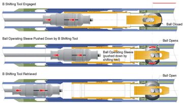
Contingency-Override-Profile Selection and Opening Direction. The barrier-valve design includes an override profile to accept a shifting tool (the “B” shifting tool) in the event that remote actuation fails and mechanical opening is required. Profile geometry is defined by the user and must be selected to interface with the minimum restriction above the device. Access required to the toe end of the completion during the life of the well also should be considered (Fig. 2).

Contingency Override Method. If remote actuation of the valve should fail, the consequence(s) of this failure will depend upon the stage at which the failure occurs. In the event of a failure to remotely close, two options are available; however, both of these will require well intervention. The first alternative method can be to use a plug to isolate the desired/required tubing section (e.g., set a plug in a landing nipple or set a bridge plug). The second alternative is to attempt to mechanically close the valve with the override shifting tool.
In the event of a failure to open remotely, the valve will also require an intervention to be opened mechanically; if this option is unsuccessful, the ball can be milled to remove the metal material and re-establish communication with the wellbore below the valve.
Verification of Valve Position. The importance of knowing whether the valve had closed or opened was recognized early in the planning phase. It was critical to gain a positive indication once the valve had been actuated during all stages of the operation; any time delay had potential to negate the cost savings and value of implementing the technology.
Operational Execution and Results
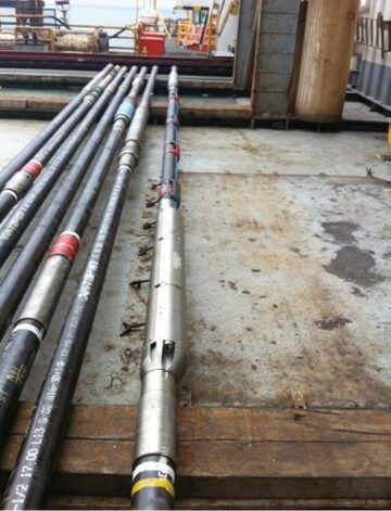
Upon arrival in west Africa, and before being shipped offshore, the remotely controlled valve was made up as a completion subassembly and was pressure tested. At the wellsite, final visual and electronic checks, which included verification of preprogrammed triggers before deployment, were completed (Fig. 3). When run into the hole in the open position, the valve allowed tubing to self-fill and provided the capability to circulate while being run into the well.

For a discussion of the sequence of steps in the installation of the upper completion, please see the complete paper.
This article, written by JPT Technology Editor Chris Carpenter, contains highlights of paper SPE 166271, “A Case Study of Using a Remotely Controlled Downhole Valve for Completion Installation,” by Keith Oddie, SPE, and John O’Hara, SPE, Halliburton, and Luis Paz, SPE, Hess Corporation, prepared for the 2013 SPE Annual Technical Conference and Exhibition, New Orleans, 30 September–2 October. The paper has not been peer reviewed.

