Paul Weddle describes himself as a “perforation geek.” The completion manager for Liberty Resources is among a small group that has an obsessive interest in all the details that can alter the performance of the openings blasted through casing, cement, and into rock during hydraulic fracturing.
The shaped charges that create circular openings with amazing force are a well-established technology that gets little notice so long as the guns go off as planned. But Weddle is among a few who see perforations as the point of attack for raising fracturing performance.
At the recent SPE Hydraulic Fracturing Technology Conference, Liberty reported completions in North Dakota that routinely stimulated more than 12 of 15 clusters, resulting in wells producing 1.7 to 2.5 times more than comparable wells (SPE 189880). By changing the way perforations were used, the operator was able to reduce the number of stages to 27 along a 9,500-ft lateral, which it estimates saved 15% on its finding and developing costs per barrel.
It stimulated those stages, which are about 350 ft long, with 15 clusters of perforations, with two perforations in each. This represents a significant break from the standard design of four or five clusters each with as many as six perforations. Since the tests reported in the paper, Weddle said Liberty has “gone all in on it.”
ConocoPhillips is working on designs with as many as 10 clusters per stage and two or three perforations per cluster, with all of them located at the top of casing, said Dave Cramer, a senior engineering fellow in completions for ConocoPhillips.
More clusters per stage allow operators to fracture longer wells without the cost of added stages, but Liberty and ConocoPhillips have not had a lot of company.
“I would say these ideas are not yet common to the industry, but at least a few operators and service companies are thinking about them,” said Robert Barree, president of Barree & Associates. The fracturing consultant said that “15 clusters are a lot. Most people are at the five to eight level … and some are at three.”
Grouping clusters with many perforations would seem to offer safety in numbers. The hard part about what is new is the old problem of directing a sufficiently strong stream of water into many small holes spread out along a long horizontal wellbore. Tight clusters of perforations can add stress that can interfere with fracture growth.
Liberty’s method depends on its ability to limit the fluid into each of the perforations to ensure that the high-pressure flow is distributed equally enough to stimulate most of the perforations. Liberty’s new method, called eXtreme Limited Entry (XLE), is based on work going back decades, including a paper in 1987 by Cramer (SPE 16189) on limited entry fracturing.
Weddle turned to Cramer last year to compare notes about Liberty’s 2-year effort with a man who could be described as a pioneering perforation geek. While Weddle was working on revamping Liberty’s fracturing design, he said there were not a lot of people focused on the perforations. But that seems to be changing since the paper.
“Based on the dialog I have had in recent years and the dozen or so calls I have received from other operators since the 2018 paper came out, there are not a lot of others doing XLE, [but] I think it will catch on quickly going forward,” Weddle said.
Typical Perforation Damage
When the charge is detonated:
- The liner of the charge is melted and partially vaporized and expelled as part of a focused jet of gases formed by the constructive interference of the reacted explosive that formed the body of the charge.
- The amount and focus of the jet displaces the steel in the casing wall, the cement behind the pipe, and the formation rock and fluid to form the perf tunnel.
- The pressure exerted by the perforating jet is immense. The time involved in the perforating event is very small (microseconds).
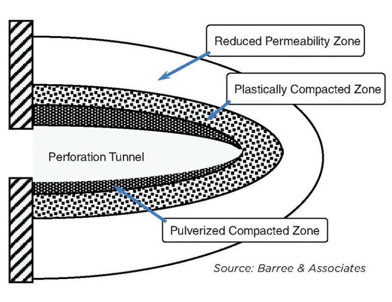
- The target rock is not vaporized, but mechanically pushed away to form the cavity. This happens so fast that the rock must deform plastically and irreversibly. The induced shock creates substantial compaction and damage around the perforation.

Stage Reductions
Putting in more perforation clusters per stage can save money. Liberty is using more clusters per stage with fewer perforations in each, allowing it to fracture longer wells with fewer stages. As wellbores have grown to 2 miles long, and then increasing to 3 miles long, completion engineers are faced with finding an alternative to spending more on additional stages.
More clusters per stage can do that, but it only makes sense if a high percentage of the more than 400 clusters are productive. “We need 330 to 350 clusters to work to deliver the pounds per cluster [of proppant] and the number of clusters needed” to meet production expectations, Weddle said.
The recent paper focused on the attention to detail required to maximize the number of perforations stimulated by ensuring that the flow continues to be limited enough to divert fluid while the flow of water and sand opens the holes. Essentially it is a race against erosion, and erosion often wins.
“As soon as sand hits perforations that are hydraulically diverted (e.g., taking fluid at 2.0 to 2.5 bbl/min per perf), the sand will erode the perfs and hydraulic diversion is sharply reduced,” said George King, distinguished engineering advisor for Apache Corp. Fracture monitoring using fiber-optic cable to monitor how much fluid each perforation is taking based on the sound of the flow showed “perfs evenly taking fluid at the start of the job and a very lopsided split of fluid injection near the end of the job,” he said.
A key finding in the Liberty paper was that the rate of erosion in its wells is significantly lower than indicated by previous papers, including the one in 1987 introducing the Cramer Erosion Model.
Fracturing methods have changed drastically since then but certain variables continue to play a major role. Cramer said three critical ones are the thickness of the casing and the hardness of the steel used to make it, and the volume of proppant per perforation.
Harder pipe wears slower, and thicker walls delay the moment when the abrasive flow creates a wider-diameter hole all the way through wall, which sharply increases the flow. There is a minimum amount of proppant required to do that—from 6,000 to 10,000 lb depending on the casing—and more proppant speeds the process.
Field data gathered by Liberty using pressure testing (step-down tests) showed a lower erosion rate in perforations likely taking in from 3.3–3.8 bbl/min in its designs. Testing is required because reality is messy. It is a mistake to assume the sand pumped will be evenly distributed among the holes and the size of those holes often varies.
Weddle said erosion is reduced by harder steel in the casing—P-110 vs. L-80—and the slickwater mix includes a relatively low number of pounds of proppant per gallon of fluid. The payoff can be more perforations stimulated, but there is a limit.
Those who believe in limited entry say it can distribute fluid and proppant more evenly, but not equally, among the perforations. The primary goal is to stimulate all the perforations. “We strive for and often achieve 100% efficiency,” Cramer said, adding, “That does not mean it [fluid] is evenly allocated whatsoever.” Some holes may get twice as much as others.
The challenges have grown as the complexity of the wells and the completions has grown. Cramer said the “scale is enormous compared to what we did in the old days.”

Perforation Evolution
Perforating creates a path from the confined environment built by drilling and completion engineers to the expansive formations imagined by reservoir engineers. But these openings have often been an afterthought.
“People tend to focus on the far-field fracture geometry and forget that a fracture must initiate at the wellbore and connect to it,” Barree said. He described the ideal perforation as “a hole through the pipe to connect the pump truck to the fracture.”
The reality is that the shaped charges send out intense jets of gases that punch a hole through the pipe and cement, then create a tunnel that is several inches long and usually a dead end.
“The common belief is fractures grow out of perforations, and what we perforate starts fractures. That is not at all what happens,” Barree said.
The shaped charges used now evolved from ones created for punching into conventional reservoirs, where the pressure and flow rates pushed oil and gas through these tunnels.

In the ultratight rock of unconventional formations, the goal is creating a pathway for fracturing fluid to flow into the formation to fracture the rock. The tunnel normally cannot do that because the force of the charge pushes aside the rock compacting it tightly. The result is a rock barrier surrounded by a “stress cage” that can interfere with fracture initiation and growth nearby.
Evidence of the problem dates back to US government-funded research back in the 1980s that dug up a large sample of fractured rock with perforations created by shaped charges. It showed fractures forming around the base of the tunnel. “That fracture went out of its way to avoid the perf tunnel every time,” Cramer said. Fracture growth will be diverted away from local high-stress features such as perforation tunnels.
Speakers at the SPE Hydraulic Fracturing Conference said studies showed that the locations where swarms of fractures are found often bear little relationship to the spots stimulated in the well. And nearly half the time the fluid injected at one stage flowed out into the reservoir at another stage.
“Which perf takes the most fluid is a crap shoot and probably depends on formation factors as much as perforation factors.” King said.
Completion engineers are trying to improve the odds by effectively stimulating more spots, and reduce the risks that excessive fracture growth can cause. This is a growing worry as new wells are drilled near older wells resulting in problems ranging from wells with overlapping drainage patterns to damaging fracture hits.
Weddle recognizes varying rock properties will determine where fractures develop. His job is “trying to take advantage of it within the bounds of what is available.”
And the details will change over time, based on what works for the business. “The focus is to figure out how many clusters we could effectively treat and then work with our multidisciplinary team to figure out how many clusters [and at what spacing] was optimum for our well economics,” Weddle said.
There is Diversion and Then There’s Diversion
A successful well can spark an argument over why it did so well. For example, a year ago Liberty Resources presented a paper about a new, improved completion design that featured diversion: chemical particles to block perforations taking in the most fluid, diverting fluid to openings that otherwise might not have been stimulated (SPE 184828).
Recently it delivered a sequel (SPE 189880) on how its completion design has evolved since then featuring a different sort of diversion: limiting the flow of fracturing fluid into the fractures during fracturing to divert fluid among all the perforations to ensure they all were stimulated.
Both papers reported strong production improvement in the Bakken, far exceeding production from comparable wells in its large database of wells in the play, and in both cases it reported that tests using tracers showed a high percentage of the clusters per stage were stimulated and producing.
But the wells in the 2018 case studies did not use dissolvable particles for diversion, and completions both years were designed for limited entry, though more so during the second round of tests.
Paul Weddle, the completion manager for Liberty who presented the papers, said the fact the second year’s test did not include chemical diversion does not mean they are backing away from the method, and they have had solid wells using both approaches.
He chooses his words carefully because there is a divide between those who believe chemical diversion works and those who do not.
On the skeptical side on chemical diverters is Dave Cramer, a senior engineering fellow in completions at ConocoPhillips, who is an expert and advocate for limited entry fracturing. Based on his experience, the problem is “particulate diversion is indiscriminate.”
The particles are supposed to flow to the perforations taking the most fluid and block them, which is known as bridging, and divert the fluid to under-stimulated locations. What Cramer has observed is “under-stimulated intervals are at significant risk of being bridged and excluded from the remaining part of the treatment.”
“The volume of chemical particles needed to divert flow from the dominant fracs will likely plug all the perforations,” he said.
Liberty’s 2017 paper at the SPE Hydraulic Fracturing Technical Conference was one of several then that concluded otherwise. The initial paper focused on using chemical particles because that was the starting point of the company’s work in 2015. That work also led to a reduction in the number of stages from 50 to 35, with more perforation clusters per stage.
Back then Weddle said they were also working on changes at the perforation level designed to limit the flow into any single perforation to divert fluid to other perforations. Some of the wells used to test diversion using chemical particles included many elements in the 2018 limited entry design.
Liberty has tried combining both the chemical particles and its limited entry method it calls eXtreme Limited Entry (XLE). Weddle said the combination delivered solid results, but has not done the work needed to measure if the combination is more or less effective than using only XLE.
While it did an internal study comparing the wells in the 2017 paper and the 2018 paper, those results were not reported. If there is a paper next year, it could offer yet another view of what works. “We are happy with our current results but always looking for what knob we can turn next to make them incrementally better,” Weddle said.
One Hand Up
When addressing a group of engineers at a completions workshop, Weddle asked how many in the room doing limited entry fracture had calculated the friction entry pressure associated with their fracturing design.
“One of them raised their hand,” he said. For Weddle that was a telling detail, because that calculation is a measure of the attention to detail required to ensure the limited entry lasts long enough to be effective.
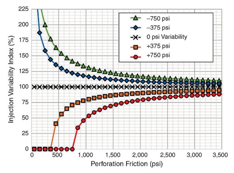
That number sums up the ability of the perforations able to restrict the flow at the beginning, with enough extra friction to provide a margin that allows it to continue to divert fluid as it erodes during pumping.
Cramer said those who fail “do not take limited entry as seriously as they should.”
Fig. 1 shows that as the level of perforation friction rises, the variation in the injection rates among the perforations decreases. Liberty shoots for a 2,000‑psi margin while ConocoPhillips targets from 1,200 to 1,500 psi. In both cases they are balancing a desire for even stimulation and the cost of building a well within their budget that can stand up to the pressure associated with their goal.

The friction value varies based on the degree of restriction (the size of the perforation hole which restricts the flow) and the things that determine the erosion rate (from the hardness of the steel used in the casing to the volume of proppant pumped through each perforation).
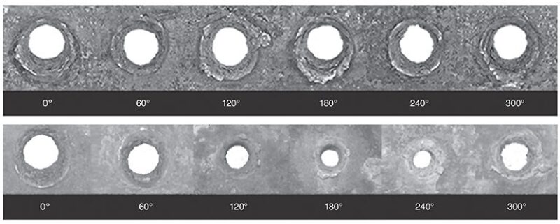
Not all perforations are created equal. The problem is that perforation guns rest on the bottom of the casing. Holes shot on the bottom of the casing are likely to grow more because they are larger to begin with and that feeds further growth.
Testing done by Geodynamics, a maker of perforation charges that supplies Liberty, showed the size ranged from 0.48 in. at the bottom of the casing tested and 0.25 in. at the top (5.5-in. inside diameter P0110 casing). Those on the sides fell in between.
Bigger holes tend to get bigger faster than small ones. That created a demand for charges that create evenly sized holes when the gun is at the low side of the casing, which are now sold by Geodynamics and others.
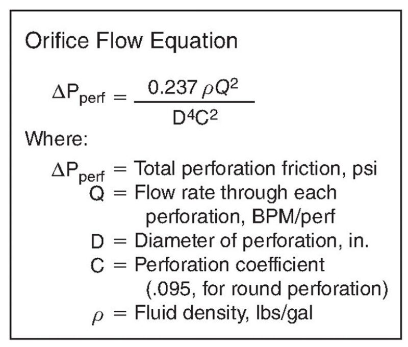
Diameter matters more than any other variable in an equation used to calculate inflows because that variable (D) is raised to the fourth power, as shown in the Orifice Flow Equation. For that reason, Liberty was an early adopter of charges that eliminated a major variable at a cost that is comparable to traditional charges, Weddle said.
Changing Parameters
When Cramer wrote a chapter for a textbook on fracturing published in 2016, he said the limit on the number of clusters was four or five per stage with about six perforations each. When he looked at what he had written recently, he said, “I need to rewrite that.”
Based on current practice, he said the limit on clusters would likely be eight to 12 and perforations would be two to three. And it would be wiser not to try to set limits for a technology in flux.
Cramer and Weddle said they are thinking about perforation clusters with only one perforation. That fracture initiation point would require a new name since one is not a cluster.
A single shot would allow more clusters per stage, eliminate concerns about hole size differences within a cluster, and allow pressure testing (step-down tests) to determine how many of the spots with perforations are performing.
If only one hole is shot, they say it should be aimed at the top. Cramer said it is likely to hit within a 60° arc around that spot. Guns are oriented using a weight bar that is not perfectly precise, which is another challenge for makers of charges that are competing to keep up with the changing needs of the business.
Geodynamics is also working on perforation charges creating holes at a 45° angle to the wellbore, based on the thinking that it would “create less of an abrupt turn and allow fluid and proppant to enter more efficiently,” said David Cuthill, a perforation simulation and technology engineer for Geodynamics.
It is hard to predict how that will perform in the ground. There has been little research about fluid flow during fracturing in and around the wellbore.
There are many studies showing the first cluster reached (heel side) will normally take in the most fluid. That is often said to be due to stress shadowing—the pressure created by fracturing previous stages limits growth from the nearest perforations—but there are also papers showing more fluid is likely to go into the first opening, leading to poor stimulation of perforations further down the wellbore. SPE 184861 concluded that fluid is more likely to leave early than sand, whose inertia is likely to carry it past the first opening.
ConocoPhillips did wells with fewer perforations on that first (heel side) cluster to limit the fluid it took in. That was no longer an option when it cut the number of perforations per cluster because the percentage difference in the volume of fluid delivered is a lot more when going from 3 to 2 perforations than when going from 6 to 5.
There is also a need to find new ways to directly observe what is going on at the perforation level, which is below the level of detail on most tests. ConocoPhillips has been working with a downhole imaging company, EV Offshore, to develop a way to efficiently image and analyze hundreds of perforations to observe the effects of erosion.
Hole widening due to erosion had been estimated based on inferred pressure data during fracturing. “When we get photos … that is another piece of the puzzle,” Cramer said.
More research is needed to understand fracture growth near the wellbore, said Roberto Suarez-Rivera, scientific advisor, W.D. Von Gonten & Co.
While operators and suppliers are working to stimulate perforations better, he said there needs to be more work done on alternatives to shaped charges.
They includes back to the future ideas like bullets, which were dropped years ago in favor of more consistently shaped charges. Bullets sound promising because they can fracture rock on impact.
Suarez-Rivera said his lab testing showed that by simply etching a line in a block of shale, which he described as a stress concentrator, it was possible to fracture it at less than half the pressure needed to fracture the unaltered rock.
More focus is needed in the near-wellbore area where the control and force of the fracturing fluid is greatest he said, adding, “The initial fracture opening has long-term consequences on the overall fracture.”
For Further Reading
SPE 189880 Mining the Bakken II—Pushing the Envelope with Extreme Limited Entry Perforating by P. Weddle, L. Griffin, and C.M. Pearson, Liberty Resources.
SPE 16189 The Application of Limited-Entry Techniques in Massive Hydraulic Fracturing Treatments by D.D. Cramer, BJ-Titan Services Co.
SPE 184828 Mining the Bakken: Driving Cluster Efficiency Higher Using Particulate Diverters by P. Weddle, C.M. Pearson, and L. Griffin, Liberty Resources.
SPE 184861 Proppant Distribution Among Multiple Perforation Clusters in a Horizontal Wellbore by C. Wu, S. Yi, and M.M. Sharma, The University of Texas at Austin.


