This paper describes various sulfide inhibitor-testing techniques that have been applied to candidate products for the management of zinc sulfide (ZnS) and lead sulfide (PbS) in a gas/condensate field with a known relatively severe ZnS/PbS scaling problem. The paper presents sulfide static- and dynamic-test measurements along with thermal-aging results that show some encouraging results in terms of ZnS/PbS inhibition.
Glenelg Field
The Glenelg field is a gas/condensate field discovered in 1999 by exploration; production began in 2006. Glenelg is located in the southern part of the central graben of the North Sea, and it is part of an area where there have been a number of gas/condensate discoveries within Jurassic and Triassic (Fulmar) sandstone formations. For a geological description of the field, please see the complete paper. The Glenelg reservoir has three producing layers (A, B, and C), with the top of the reservoir at approximately 5815-m true vertical depth with diverse reservoir characteristics: thickness ranging from approximately 50 to 150 m, porosity of between 13 and 17%, permeability between 0.3 and 60 md, and water saturations in the range of approximately 28–89%.
Scaling-risk studies for Glenelg show that the primary scaling risk is from calcium carbonate (CaCO3) both in the well and in the production facilities, with halite in the production facilities attributable to the high salinity, as is the case with other high-pressure/high-temperature gas/condensate wells nearby. However, pressure/volume/temperature studies showed hydrogen sulfide (H2S) content at approximately 30 ppm, with anticipated levels of H2S at approximately 55 ppm during production, although approximately 5 ppm was measured from core barrels. The petrographic reservoir-characterization and -connectivity study shows evidence of pyrite, sphalerite, bitumen, and iron minerals in the reservoir. The presence of H2S is indicated to be as a result of thermochemical sulfate reduction.
The source of the sulfide ions and metal ions can be traced in part to the cements in the reservoir rock structure obtained through core analysis. The main cements are quartz, carbonates (dolomite), sulfides (pyrite framboids, sometimes associated with minor amounts of sphalerite), and minor bitumen contents, which mainly occur below the gas/water contact. The maximum H2S gas recorded during the well testing was approximately 50 ppm, with CO2 at approximately 4%. Where Zn and Pb occur in the Glenelg-produced brines, this level will induce the formation of ZnS and PbS in the production stream.
Scale-control strategies adopted for the Glenelg field involve the following:
- Selection and application of preventive scale inhibitors suitable for both CaCO3 and sulfide scales, or selection of compatible (preferably synergistic) scale inhibitors for CaCO3 and sulfide scales.
- The selected scale inhibitor should be compatible with the high-salinity brine at greater than 200 000 mg/L.
- The selected scale inhibitor must be thermally stable for Glenelg conditions at 180°C.
- The selected scale inhibitor should be squeezable and retain its stability when squeezed in the reservoir.
- The selected scale inhibitor must not produce additional H2S gas for reasons related to health, safety, and the environment.
- For a discussion of the experimental procedure, equipment, and analysis, please see the complete paper.
Scale-Inhibitor Selection and Performance
An initial laboratory study was carried out to screen selected scale inhibitors with the potential to inhibit CaCO3 scale and to disperse sulfide scales. Candidate chemicals were screened using North Sea seawater (NSSW) and formation-water compositions, with added Pb, Zn, and H2S as appropriate. As this testing program proceeded, the best-performing scale inhibitors were tested in more-severe compositions/conditions and the poorer-performing chemicals were dropped. A wide range of scale inhibitors and potential sulfide-dispersal chemicals was received from various vendors, including a number of polymeric and phosphonate-based inhibitors.
Static-Inhibition-Efficiency-Test Results. An initial series of inhibition-efficiency bottle tests was carried out on approximately 40 scale-inhibition/dispersal chemicals. From this study, it was established that a series of polymeric inhibitors (denoted P1, H1, H2, and H3) were more effective inhibitors than any of the other chemicals for Zn and Pb sulfide scales. These chemicals were progressed to the next stage of the static-inhibition evaluation, where more sensitivity experiments with conditions closer to those of the Glenelg field were used to further evaluate P1, H1, H2, and H3. Brine compositions and test conditions for the initial broad scale-inhibitor selection (NSSW) are discussed in the complete paper.
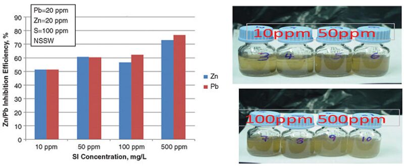
Fig. 1 shows the inhibition efficiency for a milder mixed-ZnS/PbS-scaling case (Pb=20 ppm, Zn=20 ppm, and excess S=100 ppm) at 10, 50, 100, and 500 ppm of polymeric chemical P1 (T=90°C). The associated photographs indicate that the sulfide is held in suspension by the chemical and does not drop out of solution. They show that the 10- and 50-ppm bottles are clearly divided, with noticeable precipitation at the base of the bottles, although some ZnS/PbS was held in solution. The same scaling cases with polymeric inhibitor chemicals H1, H2, and H3 (T=90°C) show improved mixed sulfide inhibition compared with the previous chemical, P1.

Having shown that H3 demonstrated some promise in simple brine (seawater) sulfide-scaling systems, the H3-type chemistry was then tested further with the more-severe Glenelg brine. Testing for a more-severe mixed-ZnS/PbS-scaling case used a brine composition with increased metal/sulfide loading (Pb=50 ppm, Zn=100 ppm, and excess S=250 ppm) at T=90°C. These tests were carried out with the polymeric H3 species for the single sulfide scales, ZnS and PbS, and also for the mixed-ZnS/PbS scaling system.
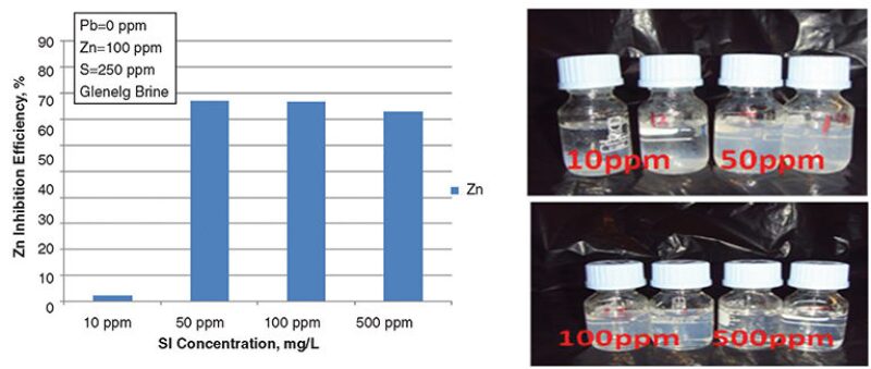
Fig. 2 shows the inhibition efficiency of H3 in a single ZnS-scaling system (Pb=0 ppm, Zn=100 ppm, and S=250 ppm) at 90°C. A drop in the H3 performance at 10 ppm was observed, but the H3 at 50, 100, and 500 ppm continued to hold the ZnS in solution, preventing precipitation. Also considered were the results of PbS-only inhibition-efficiency tests for H3 (Pb=50 ppm, Zn=0 ppm, and S=250 ppm) at 90°C. Again, there is a drop in performance at 10 ppm when compared with the results of the seawater-brine test, and, as in the ZnS-only test, the 50-, 100-, and 500-ppm-concentration levels prevented the PbS from precipitating. Inhibition-efficiency experiments for H3 in a mixed ZnS/PbS system (Pb=50 ppm, Zn=100 ppm, and S=250 ppm) at 90°C show that H3 is very effective in preventing the deposition of scales at 50 ppm in both single- and mixed-sulfide systems; this finding prompted further tests of H3-type chemistry.

For a discussion of dynamic-inhibition-performance tests, please see the complete paper.
Stirred-Vessel Dynamic Test of H3 in the Presence of PbS, ZnS, and CaCO3 Scales. In this system, the dynamic vessel in Fig. 3 above was used and the calcite deposits on the spindle were analyzed to observe the nature and state of the deposited calcite scale. Calcite crystals formed on the metal surface in bulk after 24 hours in the vessel using brine compositions with Ca=20,000 ppm, Pb=0 ppm, Zn=0 ppm, and S=0 ppm. The crystal shape of the calcite showed no distortions, although crystal aggregation was noted in the bulk. When CaCO3 crystals were coprecipitated with PbS and ZnS using the brine compositions with Ca=20,000 ppm, Pb=50 ppm, Zn=100 ppm, and S=250 ppm, they were highly distorted and covered in a sheen of PbS and ZnS on the metal surface. The bulk calcite produced with PbS and ZnS and the CaCO3 crystals were distorted, and calcite was not aggregated in the bulk. 1,000‑ppm H3 was then added to the brine to prevent PbS and ZnS deposition under the same conditions (brine compositions with Ca=20,000 ppm, Pb=50 ppm, Zn=100 ppm, and S=250 ppm) but with CaCO3-crystal formation. Under these conditions, the CaCO3 crystals were significantly distorted to round/spherical crystals, and fewer crystals were deposited on the metal surface. The calcite precipitated in the bulk, on the other hand, was visually more rounded, unlike the base case. The CaCO3 crystals were of different sizes with smooth edges, indicating that severe distortion of these crystals was caused by the presence of the H3 chemical.
When 500 ppm of H3 was added to prevent PbS and ZnS (Ca=20,000 ppm, Pb=50 ppm, Zn=100 ppm, and S=250 ppm), the resulting CaCO3 crystals were again significantly distorted to round/spherical crystals. The precipitated CaCO3 crystals deposited on the metal surface were aggregated together. When CaCO3 was coprecipitated with ZnS/PbS (Ca=20,000 ppm, Pb=50 ppm, Zn=100 ppm, and S=250 ppm) and 10 ppm of H3, the deposited crystals on the metal surface showed signs of surface pitting and the crystal surface appeared to be distorted even at a low dose.
The results from the tests in this simple dynamic vessel indicate that, even at low doses of H3 of approximately 10 ppm, the chemical still had a significant effect on the CaCO3-crystal morphology.
For a discussion of inhibitor-thermal-aging-test results, please see the complete paper.
Summary and Conclusions
Four main products were identified as having some sulfide inhibition for severe mixed ZnS/PbS scales. Of these species, H3 worked under the most-severe sulfide-scaling conditions tested here (Zn=100 ppm, Pb=50 ppm, and S=250 ppm). The next-best product showed some performance in the lower-sulfide cases (S=5 ppm). The other two products also showed some limited activity, but at a much lower level than other products.
Testing of CaCO3-inhibition properties of product H3 was also carried out. H3 exhibited some inhibition, but it did not stop CaCO3-scale formation, although it did have some effect on CaCO3-crystal morphology.
Although the H3 product performed best for the most-severe ZnS/PbS cases studied in this work, it was found to be thermally unstable when aged over a period of 11 days at 180°C. However, some sulfide-inhibition performance remained when the predegraded H3 was applied at higher concentrations (H3=approximately 500 ppm).
This article, written by JPT Technology Editor Chris Carpenter, contains highlights of paper SPE 169798, “Sulfide-Scale-Formation and -Inhibition Tests for a Gas/Condensate Field With Severe Scaling Conditions,” by Cyril Okocha and Kenneth S. Sorbie, Heriot-Watt University; Christian Hurtevent and Salima Baraka-Lokmane, Total; and Marcus Rossiter, Total E&P, prepared for the 2014 SPE International Oilfield Scale Conference and Exhibition, Aberdeen, 14–15 May. The paper has not been peer reviewed.

