To increase deepwater-drilling-rig availability, operators have adopted the strategy of transferring subsea-tree-installation responsibility from offshore drilling rigs to subsea-equipment-support vessels (SESVs). The installation from a rig can take 1 to 3 weeks; transferring this responsibility to the support vessel enables the rig to move to the next well sooner and offers significant time savings. This paper introduces a fit-for-purpose surface-controlled formation-isolation valve (SFIV) designed for the temporary well suspension required for this strategy.
Introduction
One of the deepwater subsea-field—development operations being transferred to SESVs is the vertical-tree installation employing the “tree-by-wire” technique. One of the key components of this technique is the use of two remotely operated formation-isolation valves that suspend the well after installation of the tubing hanger. Once the well is suspended, the rig can be moved to the next well. The tree is then installed by use of a heave-compensated wire from an SESV.
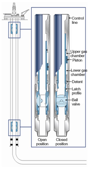
A new generation of SFIVs has been designed to enable the well suspension involved in this technique (Fig. 1). Several critical requirements were considered in the development of these valves:
- Reliable bidirectional sealing.
- Repeatable remote operation.
- Fail-as-is: In case of a failure in the control system or the valve itself, the valve must not change its position.
- Ability to open under high differential pressure.
- High debris tolerance.
Two sizes of SFIVs were developed that meet these requirements. These were fully field tested in 2011 and 2012 in 11 different field installations.

Design and Key Features
The ball section of the SFIV is designed to tolerate the debris common in harsh well environments. The SFIV uses a nontranslating ball valve with bidirectional sealing, which is the ideal valve system for high-debris environments. The ball-valve primary seal is a gas-tight seal and sustains its integrity even after repeated actuations under pressure differentials.
To allow for increased setting depth, the SFIV actuation section uses a displacement-based fail-as-is mechanism, which functions independently of the setting depth. Most other lubricator valves use a holding system that counteracts the hydrostatic pressure in the event of a control-line leak. At extreme depths, the hydrostatic force acting on the actuation piston creates a large force, increasing the holding force for the valve position as well. This can create operational issues. With the increased holding force, the actuation force must also increase, and with pressure limitations on hydraulic lines, this can take the valve outside the hydraulic operating envelope. To overcome these limitations, the SFIV was designed with a multicycle piston actuation. This enabled inclusion of a fail-as-is feature: If a control line leaks, the valve will move into a passive “dummy” position rather than actuating. This is achieved by use of an independent piston that is not attached to the operator mandrel. The cycle mandrel also accommodates the use of a large balanced piston, which enables operation of the valve at any depth while maintaining low operating pressure from the hydraulic lines.
Testing
The ability to open the SFIV under high differential pressures was a key design requirement because pressure can be trapped between the two valves during the well suspension. The design requirement included multiple open and close operations with 2,000-psi pressure differentials across the ball. The functioning of ball valves under differential pressure creates a unique design challenge because of the increased friction on the ball seal that results from the differential pressure. This friction, combined with the large cross-sectional area, creates large forces that must be overcome. A large balanced piston enables operation with low hydraulic pressures even under large differential pressures.
The testing of the valve consisted of applying 2,000 psi below the ball and actuating the valve while maintaining this pressure. The valve was then closed and retested to ensure seal integrity after operating under the differential pressure. The valve design incorporates two dummy cycles before opening to provide the fail-as-is feature.
Testing was also performed to evaluate debris tolerance and endurance. Typical debris-tolerance testing for formation-isolation valves consists of filling the valve with debris and performing a one-time actuation. However, because of the repeatable-function requirement, a test was designed using sand--slurry testing as a basis. Testing consisted of 10 slurry flows of 1 hour each with a sand content of 2% at various flow rates between 2,000 and 3,000 B/D. After each interval, the valve was closed and tested from above and below with 200 psi, with 50% of working pressure, and at working pressure, for a total of six tests per interval and a total of 60 tests with 10 actuations. All tests were successful. In addition, the SFIV was fully qualified by a series of tests for high and low temperature limits, temperature cycles, burst and hydrostatic pressure, bubble-tight barrier seal, vibration, and shock.
Installation
The SFIV is installed using the usual procedures of control-line-bearing equipment, with the option to run the lines pressurized or nonpressurized.
While running the completion, the SFIV can be cycled multiple times. This allows the equipment and tubing above it to be pressure tested and eliminates the need for dedicated tubing-testing devices or slickline to install temporary plugs, providing savings in logistics, material, and time. After the completion is landed, the SFIVs are cycled to the closed position and act as barriers for well integrity during the suspension.
Upon the installation of a subsea tree with the SESV, confirmation of the valve-opening operation is crucial for successful production startup. The ability to open the valve under differential pressure enables pressurization of the tubing above the valve and cycling by use of a control line. A pressure drop in the tubing is a positive confirmation of opening.
During production at significant depths, if a permanent downhole gauge is installed below the SFIV, on-demand buildup tests can be performed by cycling the valve closed and observing the pressure trend in the gauge. Once the test is finished, the valve can be reopened, even if there is high differential pressure.
Case Study: Operational Efficiency
In the case study, the tree-by-wire subsea vertical-tree-installation technique was compared with the standard method in terms of operational efficiency to evaluate the contribution of the SFIV. The data are based on the experience from the initial installations.
Completion With Standard Vertical-Tree Installation. The well--completion operation fully executed from a rig can be summarized in main steps, from lower completion to tree-cap installation. Table 2 in the complete paper lists these steps. The rig leaves the location only after all operations are completed. Logistics are complex because a supply vessel has to move all the equipment from the port to the rig. Weather conditions can delay material transfer and add total time to the operation. As operations scale up, the ports will also face challenges to timely performance of all operations, presenting another potential lost-time source.
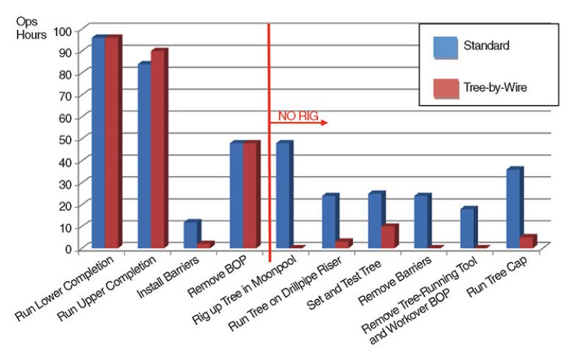
Completion With Tree-By-Wire -Vertical-Tree Installation. In this installation, the specialized SESV substitutes for the rig after the blowout preventer (BOP) is removed. The rig leaves the location and is able to start operations on another well. The vessel is designed to run the subsea tree and its installation apparatus on a cable and to lower it by a winch. Operational time is much lower than running the tree and installation apparatus through completion risers, which is the typical rig operation.
The main challenge of an upper-completion design is how to manage the safety barriers used to secure the well between the removal of the BOP and installation of the tree. Considering that the SESV has no intervention capability inside the production string, the use of slickline plugs or standing valves is not desirable because this would imply another rig intervention. Therefore, remote demobilization of the barriers is necessary. After the tree--setting and testing procedures, the SFIVs are opened and the well is ready for the startup process from the production vessel that will be connected later. The valves are hydraulically opened by control-line pressure cycles without any well intervention.
The logistics are simpler because the vessel boards up to six systems at once at the port and then performs the installation campaign. The tree-rigup operation is transparent because while one system is installed, the next is being prepared.
From the operational point of view, not only are 7 rig days saved, but the rig is available for another operation. Fig. 2 demonstrates the drop in operational time when the installation service is performed by an SESV. Considering the daily rig rate as USD 500,000, savings are USD 4.2 million, at the expense of 1.4 days of SESV operation for USD 200,000/D—a net savings of USD 3.92 million.

Results
The first field test was performed in 2010 with a suspension time of approximately 1 month. The completion was installed successfully without issue. Both valves were actuated multiple times before reaching depth and actuated and tested in the closed position before the rig departure. Upon completion of the suspension period, the vertical tree was run to depth and the valves were opened without issues. The valves were installed successfully and used as suspension and lubricator valves.
One of the key features of the valve is its ability to open under 2,000-psi differential pressure. This feature was verified through rigorous testing. Its significance was demonstrated during the field installations when the valve had to be opened at differential pressures of 500 psi.
For long-term suspensions and for production testing, debris tolerance is critical. During debris testing of the valve, there were no operational issues related to debris even during the installations that involved suspension times of more than 3 months.
Another key requirement of the valve is ease of operation. In all the installations, the valves were operated from the rig and from the SESV without any problems.
The fail-as-is feature provides full confidence that the risk of accidental opening or closing of the valve is minimal during the long suspension periods or during production.
This article, written by JPT Technology Editor Chris Carpenter, contains highlights of paper OTC 23997, “Case Study: Surface-Controlled Formation-Isolation Valves and Their Application as a Barrier for Temporary Well Suspension,” by Oguzhan Guven, Joao Mendonca, and Dan Thai, Schlumberger, prepared for the 2013 Offshore Technology Conference, Houston, 6–9 May. The paper has not been peer reviewed. Copyright 2013 Offshore Technology Conference. Reproduced by permission.

