In 2010, exploration of gas-rich and possibly liquid-rich shale reservoirs began in northern Mexico. A two-stage integrated workflow was developed to achieve set objectives. The drilling stage used a petrophysical and geomechanical static model to identify the most prospective interval in the reservoir, define the best drilling azimuth and landing point, and reduce drilling risk. Real-time geosteering was implemented to achieve the targeted navigation window. In the completion stage, reservoir-centric completion-and-stimulation software was used to optimize completion and stimulation design.
Introduction
The initial target formation was the Upper Cretaceous Eagle Ford; the second was a Jurassic formation locally called Pimienta.
The Eagle Ford shale is a Late Cretaceous hydrocarbon-producing formation composed of organic-rich calcareous mudstones with mineralogical composition with ranges of 5–20% quartz, 15–25% clay, and 65–80% carbonate, and with a total-organic-carbon (TOC) range of 1–6%. The Eagle Ford shale is overlain by the Austin chalk and overlies the Buda limestone. It has been divided into two units, a lower unit deposited during transgressive sequences and an upper unit deposited in a regressive sequence. Both units were deposited in a low-angle sloping ramp. As of July 2012, five wells had been drilled in the Eagle Ford formation: AEF, BEF, CEF, DEF, and EEF.
The origins of the Pimienta formation date to the Late Jurassic. It is an organic-rich source rock with potential for hydrocarbon production as an unconventional reservoir. Its mineralogical composition exhibits ranges of 20–40% quartz, 25–45% clay, and 20–40% carbonate, with an average TOC range of 3–4%. As of July 2012, one well (AP) had been drilled in the Pimienta formation.
Methodology: Implementation of a Multidisciplinary Workflow
The implementation of the workflow was divided into four phases, as follows:
- Phase I: predrill modeling
- Phase II: geosteering and real-time monitoring
- Phase III: completion design, hydraulic-fracture modeling, and execution
- Phase IV: evaluation of well performance
Phase I. A 1D mechanical Earth model (MEM) applied to hydraulic fracturing was used to integrate all available data and to describe more accurately the in-situ stress, the workflow for the geomechanical model, and the integration of the information. For a detailed description of the work performed in this phase, please see the complete paper.
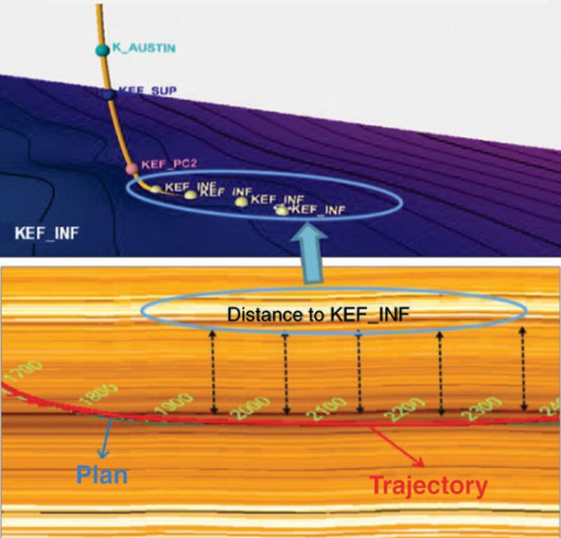
Phase II. A fine-scale structural 3D model was built for each well; these models were constructed using all the available information (well logs, 2D- and 3D-seismic data, petrophysical evaluations, and stratigraphic well tops). The first objective of this model is to complement logging while drilling (LWD) of the horizontal section. Additionally, to improve the efficiency of well placement, risks and time consumption for decisions made while steering the well were reduced by implementing real-time geological and petrophysical monitoring. The horizontal-drilling techniques applied incorporated the use of new technologies that allowed analysis of real-time data, which helped in making the best decisions to minimize risk and avoid a possible well-placement incident. Understanding the behavior and petrophysical properties of the formation being drilled is the main benefit of the real-time petrophysical evaluation, which will result in a quantification of formation quality in real time.
The structural model, coupled with the real-time geological and petrophysical monitoring, is used to determine whether the well trajectory is following the pay zone. The stratigraphic surfaces of the model can be updated with the information coming from LWD, resulting in a more-realistic structural model (Fig. 1).

Once the horizontal well is already drilled and the petrophysical analysis, stratigraphic tops, and updated geomechanical model are obtained, the static model is updated and the petrophysical properties are populated. This updated model will then be used in the simulator for the hydraulic-fracture design.
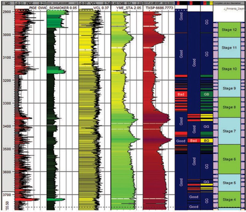
Phase III. Reservoir-centric completion-and-stimulation software that integrates petrophysical and geomechanical data was used to optimize the completion and hydraulic-fracture design. Historically, staging has been performed geometrically, equally spacing perforation clusters along the lateral. However, recent studies suggest that placing perforations in rocks with similar properties will improve distribution of hydraulic fractures along the well and, therefore, increase well production. Therefore, staging design was performed by use of the completion-adviser module of the completion-and-stimulation software. An example of the output of the stage-design process can be observed in Fig. 2.

Once the staging has been defined, the hydraulic-fracture treatments are designed. The software used is capable of simulating the behavior of hydraulic fractures in unconventional reservoirs and considers the data gathered in all of the previous phases of the workflow. The simulations were performed for each stage, considering formation properties specific to that stage and along the length that the hydraulic fractures develop. Results of the simulations were observed in a 3D interface to evaluate coverage and other required parameters along the lateral. Once the designs were finalized, the jobs were executed.
Phase IV. After the wells are opened to production, results are analyzed with various techniques. These include microseismic monitoring, production-history matching, production logging, and well testing. The results of each of these analyses are coupled with the data gathered during the execution of the fracture jobs to calibrate the model and update the hydraulic-fracturing simulations.
Application and Results
Of the six wells that were drilled and completed, the workflow was fully implemented in three and partially implemented in one. In Wells BEF, DEF, and AP, both the drilling and the completion stages were implemented. In Well EEF, only the completion stage of the workflow was implemented. The following paragraphs summarize the methodology applied and the results achieved in two of these wells (the complete paper contains this information for all four wells in which the workflow was involved).
Well BEF. This well was placed near the borderline between the expected condensate and oil windows of the Eagle Ford shale. All phases of the workflow were applied on this well. The total measured depth (MD) was 10,400 ft, and the true vertical depth (TVD) was approximately 5,085 ft, with a lateral length of approximately 4,300 ft. The well was landed and navigated in the lower Eagle Ford shale with an azimuth mostly parallel to the expected minimum--horizontal-stress direction, where the estimated reservoir properties included the following:
- Pressure: 2,800 psi
- Temperature: 169°F
- Permeability: 200 nd
- Effective porosity: 1–8%
- TOC: 3–6%
In this case, the strategy was to navigate the well approximately 16 ft below the top of the lower Eagle Ford formation to contact both the lower and upper Eagle Ford formations with the hydraulic-fracture jobs. However, this also meant that the well was placed approximately 80 ft above the “sweet spot” identified in the petrophysical analysis of the lower Eagle Ford. To simulate the behavior of the hydraulic fractures properly, an anisotropic MEM was created to estimate the stress profile, which showed considerable differences when compared with the isotropic geomechanical model that is commonly used. The engineered completion design considered 14 stages with six perforation clusters per stage, except for Stages 7 and 8, where only four clusters were used. As mentioned previously, the perforation clusters were located along the lateral by considering similar rock properties. The first stage was perforated by use of an abrasive perforation system with coiled tubing, and the remaining stages were perforated by use of the plug-and-perforation technique with pump-down guns. All stages were hydraulically fractured by use of the channel-fracturing technique. The proppant types used were a combination of 40/70- , 30/50- , and 20/40-mesh white sand. The jobs were pumped at 55 bbl/min with 180,000 lbm of proppant per stage. A total of approximately 2,520,000 gal of fluid was injected in the well.
During the flowback period of approximately 40 days, and after having recovered approximately 20% of the fluid injected, the well showed intermittent production of gas and condensate, which stopped after 11 days. To analyze this behavior, the well was closed for 16.5 days and a buildup test was performed. Interpretation of the buildup test showed a well fractured with infinite-conductivity fractures along the lateral. It is suspected that the main reason for the poor production behavior of the well is that it was not landed in the sweet spot, but rather in poor-quality rock.
Well EEF. This well was drilled inside the expected condensate window of the Eagle Ford shale. Only the last two phases of the workflow were applied on this well because it had already been drilled when analysis began. The total MD was 12,320 ft, and the TVD was approximately 6,772 ft, with a lateral length of approximately 4,900 ft. The well was landed and navigated in the lower Eagle Ford shale with an azimuth mostly parallel to the expected minimum-horizontal-stress direction. The estimated reservoir properties included the following:
- Pressure: 4,000 psi
- Temperature: 167°F
- Permeability: approximately 200 nd
- Effective porosity: 3–9%
- TOC: 3–5%
The engineered completion design considered 16 stages with five perforation clusters per stage. The perforation clusters were located along the lateral on the basis of similar rock properties. The first stage was perforated by use of an abrasive perforation system with coiled tubing, and the remaining stages were perforated by use of the plug-and-perforation technique with pump-down guns. The first eight stages were stimulated with slickwater fractures. Because of some pressure spikes observed during these stages, the remaining stages combined the use of slickwater and linear gel to place the proppant in the formation. The proppant types used were a combination of 100- and 40/70-mesh white sand. The jobs were pumped at 65 bbl/min with 350,000 lbm of proppant per stage. A total of approximately 5,160,000 gal of fluid was injected into the well. During the production test, the well had a peak gas production of 4.6 MMscf/D and a peak condensate production of 146 B/D, while flowing by 28/64- and 26/64-in. chokes, respectively. The average wellhead pressure was 2,265 psi.
Conclusions and Lessons Learned
- The integration of several disciplines is required to design and optimize unconventional shale wells properly.
- The workflow used improves the design, evaluation, and optimization of unconventional shale wells.
- The presence of hydrocarbons in the Eagle Ford and Pimienta formations was evidenced in all the wells where the workflow was applied.
- The production results suggested that proper landing and navigation of the well within the sweet spot of the target formation are key to achieving the expected production.
This article, written by JPT Technology Editor Chris Carpenter, contains highlights of paper SPE 164545, “Unconventional-Reservoir Development in Mexico: Lessons Learned From the First Exploratory Wells,” by P.A. Parra, N. Rubio, C. Ramirez, B.D. Guerra, V.A. Exler, I.R. Campos, M.D. Trejo, J. Olguin, C.H. Vargas, R. Valbuena, D.F. Soler, M.I. Weimann, V. Lujan, and P. Bonningue, Schlumberger, and P.G. Reyes, R. Martinez, R. Muñoz, E. Rodriguez, and M. Garcia, Pemex, prepared for the 2013 SPE Unconventional Resources Conference—USA, The Woodlands, Texas, USA, 10–12 April. The paper has not been peer reviewed.
