
Deepwater cementing becomes increasingly challenging as drilling operations move to greater water depths and more-remote locations. Before the first exploration well for an operator offshore Tanzania was spudded, an extensive cementing-operations risk analysis was performed. The risks determined were low temperatures at seabed, unconsolidated formations close to seabed, potential shallow gas, and likely presence of hydrates. To drill further sections successfully, objectives were identified as zonal isolation across the shallow-flow and hydrate zones, cementing back to seabed, and good cement around the casing shoe.
Introduction
Block 2 (Fig. 1) is located southeast of Tanzania’s capital, Dar es Salaam. The water depths in Block 2 vary from 1000 to 3000 m. The target is an excellent-quality sandstone gas reservoir with very large potential. The seabed consists of soft clays and silts with minor sandy intervals. Shallow hazards were identified for this block from seismic data.
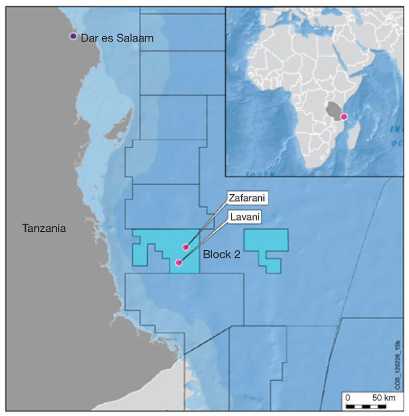
Preparation for the exploration phase started in 2007 when the license for Block 2 was awarded. Two exploration wells have been drilled in Block 2 offshore Tanzania to date. The wells were drilled in ultradeep water, with respective water depths of 2419 and 2627 m. Both wells were drilled successfully and have found commercial gas reserves.
Well Design
The well design for both wells was jetting a 36-in. conductor casing to provide sufficient well-bearing capacity. The surface casing was set deep enough to isolate all shallow zones with potential hydrates and shallow water and gas flow. The intermediate string was set above the top of the target reservoir, and the reservoir was drilled and plugged after the reservoir was evaluated. Both exploration wells were drilled vertically to total depth. The riserless section was drilled with seawater and water-based mud, while the deeper sections were drilled with a synthetic-based mud.
Challenges
The main challenges for the two wells were related to the great water depth (low fracture gradients and low temperatures) and the risk of encountering hydrates and potential shallow flows, which would need to be isolated by the surface casing.
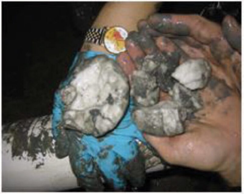
Gas Hydrates. Gas hydrates are crystalline solids (Fig. 2). They consist of a gas molecule surrounded by a cage of water molecules. Many gases have molecular sizes suitable to form hydrate, including such naturally occurring gases as carbon dioxide, hydrogen sulfide, and several low-carbon-number hydrocarbons, but most marine gas hydrates that have been analyzed are methane hydrates. Gas hydrates are naturally found when three conditions are found at the same time and place: (1) the presence of gas-hydrate formers, (2) the presence of water, and (3) pressure and temperature within the domain of stable gas hydrates.
Shallow Flow. The risk of shallow flow was highlighted for both wells after the interpretation of seismic data. Thin sand layers were identified as potential zones for shallow gas. Also, the slight risk of shallow water was identified for each well.
Remote Operations. Logistics were very challenging because of the remoteness of the operations. Engineering support for the project was provided out of Dar es Salaam. The operating base is in Mtwara, located in the south of Tanzania. Slurry laboratory testing was initially performed at service-company laboratories in Cape Town, South Africa, and Aberdeen. During the project, the laboratory in Mtwara was upgraded and became able to perform most tests required for deepwater cementing. All equipment and materials had to be ordered in advance; lead times for common items are 3 to 6 months and are longer for specialty products.
Cementing Design
A study was initiated to determine optimum slurry design and ensure that annular temperatures stayed within the gas-hydrate-stability zone during cement placement and the cement-hydration period.
Slurry Design. The formation-pressure and -strength prognosis indicated a normal pore pressure of 8.6 lbm/gal in the upper sections of the hole. The overburden and fracture gradient followed a normal trend, with an expected fracture gradient of 8.6 lbm/gal at seabed and 9.8 lbm/gal at the surface-casing setting depth. To avoid losses close to seabed, the density of the lead slurry was optimized at 12.0 lbm/gal.
The temperature at seabed was determined to be 3°C. The geothermal gradient in the first 1000 m below seabed was 5.4°C/100 m, and the gradient would decrease after that. The expected bottomhole static temperature (BHST) at the surface-casing setting depth was 34°C. Computer simulations showed a BHST of only 7°C. For the cement to develop compressive strength quickly, to be able to continue drilling operations, a neat 15.8‑lbm/gal tail slurry was placed around the shoe. Special low-temperature additives were used to enhance the development of compressive strength at low temperatures.
The slurry design for the surface casing needed to (1) be lightweight to avoid losses, (2) develop quick compressive strength at low temperatures, (3) be gas-tight to overcome the potential shallow-flow hazards, and (4) have a low heat of hydration to avoid destabilizing the hydrates. The main focus during the early design stages was on selecting the proper slurry for cementing the gas-hydrate zone.
Higher temperatures or lower pressures than those under equilibrium can destabilize gas hydrates. This can happen during and after cementation. The parameters to consider include the following:
- The total heat released during cement hydration, which depends on the amount of reactive material per volume of slurry
- The speed at which the heat is released, which depends mainly on wellbore temperature and additives
- The dissipation flow, which depends on well geometry and fluid and formation thermal properties
A number of techniques exist for determining the heat of hydration of a setting-cement system, some of them being standardized. Studies show that for the same slurry density, the heat of hydration of extended slurry is 1.5 times higher than that for an optimized-particle-size-distribution (OPSD) cement or for a foamed cement, both of which have very similar heat of hydration.
Some guidelines exist for designing slurries for the case of shallow-flow zones. The slurry must be stable, with zero free fluid and no sedimentation. It must have good fluid-loss properties; less than 50 mL/30 min is generally recommended. The transition of the critical hydration period must be minimized for the cement to develop from the critical static gel strength (CSGS) to a static gel strength of 500 lbf/100 ft2 in less than 45 minutes. The OPSD blend was optimized to meet these criteria. Liquid additives were used to provide low fluid loss at the anticipated bottomhole circulating temperature (BHCT).
On the basis of these results, an OPSD-cement system was selected to cover the hydrate zone offshore Tanzania.
Temperature Simulations. To ensure that the temperatures in the annulus stayed within the stable zone, the temperature in the annulus of the 26-in. open hole (OH) was simulated. Ocean temperatures and current velocities were derived, and a worst-case, higher-than-actual geothermal gradient of 6.4°C/100 m was assumed. Actual job design and slurry properties were used for the simulation, and an experimental measured heat of hydration was used to estimate the change in temperature during the cement-setting phase.
Results for the 26-in.-OH section show that the upper bound slightly exceeds the gas-hydrate-transition temperature in the case of very high pore-water salinity. Thus, unless unusual salinity exists, the risk of gas-hydrate dissociation while cementing the 26-in.-OH section appears to be low.
Execution
Zafarani 1. After jetting the conductor casing, the 26-in.-OH section was drilled from seabed at 2627 m to 3098 m, with a maximum deviation of less than 1°. The top section was drilled with seawater to minimize the disturbance of the hydrates. Extra care was given to keep the salinity of the seawater and sweeps as low as possible to avoid dissolution of hydrates. The well was displaced to a weighted pump-and-dump (PAD) mud before drilling through the potential overpressured zone.
Because the wellbore was drilled nearly vertically, centralization focused on a good shoe and good standoff across the potential flow zones and the hydrate interval. The casing was centralized by use of five centralizers, with a minimum standoff of 61%.
The cement job was executed as an inner-string job. The casing was run with seawater, and, after landing, the inner string was displaced with PAD mud. After landing the casing, the well was circulated to break any gels in the PAD mud to ensure good flow around the casing. Volumes were based on OH plus 150% annular excess. A volume of 150 bbl of a 10.9‑lbm/gal weighted spacer was pumped ahead of the slurry, followed by 510 bbl of gas-tight 12.0-lbm/gal OPSD-blend slurry. A 144-m section of tail slurry was placed around the casing shoe. Software simulation showed good cement coverage across the entire wellbore.
Lavani 1. A pilot hole was drilled before spudding to investigate the presence of overpressured sands; when none were encountered, the section was drilled with seawater. Only the last 15 m of the hole was drilled with a 10.9-lbm/gal PAD mud. The 26-in.-OH section was drilled from seabed at 2419 m to 3015 m, with a maximum deviation of 1.4°.
The casing was centralized by use of 20 centralizers, with a minimum standoff of 59%. The casing was run with seawater, and, after landing, the inner string was displaced with PAD mud. After landing the casing, the well was circulated to break any gels in the PAD mud to ensure good flow around the casing.
The cement job was executed as an inner-string job. Volumes were based on OH plus 150% annular excess. A volume of 150 bbl of a 10.9-lbm/gal weighted spacer was pumped ahead of the slurry, followed by 797 bbl of gas-tight 12.0-lbm/gal OPSD-blend slurry. A 100-m section of tail slurry was placed around the casing shoe. Software simulation showed good cement coverage across the entire wellbore.
Cement-Job Evaluation
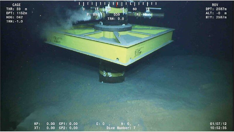
Zafarani 1. The job was executed as per design, except for a small pump-rate decrease caused by bulk-transfer conditions on location. Cement returns were confirmed by a remotely operated vehicle (ROV) during the job (Fig. 3), and no gas was observed during the setting of the cement. The wellhead was stable, and the blowout preventer (BOP) was connected without problems. The formation-integrity test showed a value sufficient to allow drilling of the next section to continue safely without any remedial work.
Lavani 1. The job was executed as per design. Cement returns were confirmed by the ROV during the job, and no gas was observed during the setting of the cement. The wellhead was stable, and the BOP was connected without problems. The leakoff test showed a value sufficient to allow drilling to continue, enabling the elimination of one intermediate string from the well design.
This article, written by JPT Technology Editor Chris Carpenter, contains highlights of paper SPE 163462, “Zonal Isolation Through Gas Hydrates Offshore Tanzania,” by J. Vølstad and T. Tveit, Statoil, and P. Aguilar, N. Hurtado, and M. Bogaerts, Schlumberger, prepared for the 2013 SPE/IADC Drilling Conference and Exhibition, Amsterdam, 5–7 March. The paper has not been peer reviewed.