
In terms of platform technologies and extraction strategies, there are fundamental differences between the North Sea and the deepwater Gulf of Mexico (GOM). We consider these systems in light of best practices in water-treating-system design and consider the reasons for deviation from those practices. This process provides insight into the design of water-treating systems in general, emphasizing the importance of carrying out effective water treatment early in the process and the necessity of using large end-of-pipe equipment when this is not possible.
Introduction
Generally speaking, there is a perception that water-treating systems in the North Sea are different from those in the deepwater GOM. Specifically, North Sea systems involve greater use of hydrocyclones, with either no flotation or compact vertical flotation. Deepwater GOM systems are associated with the use of hydrocyclones (but to a lesser degree than in the North Sea) and the use of large horizontal multistage flotation. While these differences are often noted, even greater differences are observed by considering the oil/water/gas-separation system as a whole. The oil/water-separation system includes dehydration of oil and deoiling of water. From the standpoint of the overall integrated oil/water-separation system, the water-treating system is only a part. If a water-treating system is considered an add-on to the overall separation-system (oil/water/gas) design, rather than an integral part, then it will invariably be tasked with a much more difficult challenge (smaller droplets, more-stable emulsions). In that case, it will require large multistage flotation and perhaps tertiary end-of-pipe equipment such as media treatment or filtration.
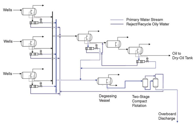
As shown in Fig. 1, a typical North Sea oil/water-treating system consists of inlet heating where necessary (not shown), followed by first-stage three-phase separation. The produced water is separated from the first-stage separation with enough pressure and is treated through hydrocyclone units.
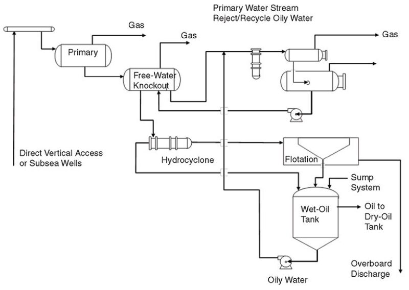
As shown in Fig. 2, typical deepwater GOM oil/water systems consist of one- or two-stage two-phase separation, followed by three-phase separation. Inlet heating is often not used. The produced water is separated toward the end of the process at lower operating pressure. The produced water is processed through hydrocyclones through a common collecting vessel operated at a lower pressure and, in many cases, a lower temperature.
The main features of North Sea systems can be summarized as follows:
- Relatively more weight and space available than in the deepwater GOM
- Relatively high arrival temperature or heat added upstream
- Several primary separators to segregate incompatible fluids
- Three-phase primary separators
- Hydrocyclones on every horizontal separator
- Hydrocyclones used upstream (on aforementioned three-phase separators), providing greater driving force for separation
- Infrequent use of hydrate inhibitors during steady-state operation
- Slightly more corrosive fluids (higher CO2 and H2S) and hence greater use of corrosion inhibitor
- Flotation flocculant added upstream of degassing vessel and downstream of any valves
- Typically compact and vertical flotation (if present)
The main features of deepwater GOM systems can be summarized as follows:
- Relatively less weight and space available than in the North Sea
- Heat added downstream of the produced-water-separation vessels
- Few primary separators (cannot segregate crude oils and water)
- Small, two-phase primary separators (sized for degassing) with no hydrocyclones on water discharge, meaning that the hydrocyclone units are operated at a lower-pressure operating limit
- Treated produced water with a higher range of smaller oil droplets of less than 10 µm
- Moderately heavy use of hydrate inhibitors and other flow-assurance chemicals
- Large multistage horizontal flotation
- Best Practice in Design of Water-Treating-Process Lineups
The term “best practices” here refers only to removing oil from water. This is a very narrow definition, which does not include capital cost, operating cost, schedule, operability, footprint, or weight. All of these factors typically, and in many cases justifiably, account for deviation from best practices.
In general, the design of a water-treating system takes the following into consideration:
- Separation efficiency of equipment and process lineup
- Capital expenses and operating expenses (cost of equipment, interconnections, chemicals, and consumables)
- Reliability, availability, and maintenance
- Weight and space
- Equipment availability (project schedule)
In theory, the term “best practice” would include all of the preceding factors. However, many of these elements are project specific, or depend on the local regulations or the financial constraints imposed on a project owing to a particular business cycle.
The following best practices for removing oil from water are given in the case where there are no other constraints on the design of the system.
- Minimize inlet shear.
- Apply heat upstream.
- Prevent solids production; separate and remove solids.
- Minimize the use of hydrate inhibitor.
- Minimize the use of corrosion inhibitor.
- Separate water early in the process.
- Provide an effective rejects-handling system.
- Provide an effective chemical-treating system.
- Provide an effective monitoring and control system.
Water-Treating-Process Lineups
The following field cases provide the initial basis upon which to understand the link between the process lineup and the effluent water quality. (For descriptions of more field cases from the North Sea and the GOM, as well as a discussion of the use of modeling tools to describe systemic differences in a quantitative manner, please see the complete paper.) The process lineup has a profound effect on the final effluent water quality. This is particularly true for offshore installations, where space and weight are constrained. In addition to the process lineup, the fluid properties, chemical-treating program, and operations strategy have important effects on final effluent quality.
North Sea. Field A. High-pressure wells (21-barg arrival pressure) are processed in a two-stage separator train comprising three-phase separators. Oily water is discharged from the first-stage separator and processed through hydrocyclones. Low-pressure wells (11-barg arrival pressure) are processed in a single three-phase separator. Oily water is discharged from the separator and processed through hydrocyclones.
Thus, all production is routed through three-phase separators, with hydrocyclones on the water discharge. The effluent from all hydrocyclones is routed to a produced-water flash tank and then discharged to the sea. Typical oil-discharge quality is 2% basic sediment and water (BS&W). Typical water-discharge quality is 20- to 40-mg/L oil content.
Field B. Oil is processed in two parallel separator trains, both with three stages, comprising three-phase separators exclusively. First-stage separators are operated at 56 barg and second-stage separators at 15 barg. Third-party oil production is also produced in the same production trains, entering at the second stage. Produced water is taken from all first- and second-stage separators and is treated in hydrocyclones, produced-water flash tanks, and flotation cells before discharge to sea. Typical oil quality to storage cells is 0.7% BS&W. Typical discharged-produced-water quality is 10 to 20 ppm oil content.
Field C. The oil is “medium-heavy oil” and is heated between first- and second-stage separators to achieve desired separation (from approximately 50°C to 70°C). The oil is processed in one separation train with four stages, with an electrostatic coalescer as the last stage. All separators are three-phase, with hydrocyclones on the water discharge. The first-stage separator is operated at 14 barg and the second stage at 10 barg. Produced water is separated from the first- and second-stage separators and is treated in hydrocyclones, a produced-water flash tank, and a compact flotation unit before discharge to sea. Typical oil-export quality is 0.5% BS&W. Typical discharged-produced-water quality is less than 10 ppm oil content (oil-droplet size is D50<13 µm for all hydrocyclone inlets).
GOM. Field A. This field was one of the first deepwater platforms in the world. Because of capital constraints, it was deployed without water-treating equipment. All inlet separators were relatively small two-phase vessels with high flux rates and short residence time. Incoming fluids were relatively cool (30 to 50°C), and heat was added only downstream for crude-oil vapor-pressure control.
For the first few years of operation, all water-producing wells were shut in. This was a reasonable strategy for several years because initial production remained essentially dry. However, when water production did commence, it rose rapidly to approximately 20%. During an 18-month period, roughly 16,000 BOPD was shut in because of an inability of the facilities to treat the water. This equated to roughly 8 million bbl of oil deferred. During this time, a project was executed to install, and shortly thereafter to expand, the water-treating system.
The water-treating-process lineup eventually included the conversion of one of the two-phase primary separators to a three-phase vessel with the addition of hydrocyclones. A produced--water flash tank was installed downstream of the hydrocyclones. A multistage horizontal flotation unit was also installed.
Field B. The process lineup for this field is typical of the deepwater GOM. As a general design strategy for this field, the high-pressure and intermediate-pressure separators are two-phase, with short residence times (and therefore high flux rates). The free-water knockout is three-phase but is also designed with a short residence time. Hydrocyclones were installed only downstream, and heat was added only downstream. Thus, the topside design was quite compact, like that of its predecessor, Platform A.
Reject from the hydrocyclones is fed to the wet-oil tank. Reject from the flotation unit is fed to a slops-oil tank and then to the wet-oil tank. Reject from the slops tank is fed to the dry-oil tank, from which it is then exported along with the platform produced oil. The slops-oil tank was used to degas the flotation reject stream and to separate oil, which could then be pumped to the dry-oil tank. Oily water from the slops-oil tank was pumped to the wet-oil tank.
Because of tight capital constraints, minimal flowline insulation was used. The typical hydrate-control strategy was to use methanol on startup. This had an adverse effect on water quality.
Historically, the average oil-in-water concentration is near 20 mg/L, and only a few sheens occur per year. The hydrocyclones operated at 70% efficiency, and the flotation unit operated at 90% efficiency.
This article, written by JPT Technology Editor Chris Carpenter, contains highlights of paper SPE 159713, “Produced-Water-Treating Systems: Comparison Between North Sea and Deepwater Gulf of Mexico” by J.M. Walsh, SPE, Shell, and W.J. Georgie, SPE, Maxoil Solutions, prepared for the 2012 SPE Annual Technical Conference and Exhibition, San Antonio, Texas, USA, 8–10 October. The paper has not been peer reviewed.