Successful development of flank areas depends on accurate reservoir characterization—in particular, water-saturation distribution—in addition to the optimal areal and vertical placement of wells. In relatively thin reservoirs, horizontal wells are generally preferred to increase reservoir contact; the proper spacing and vertical placement of these wells are critical. To test the initial concept in the field, two existing producers were converted into injectors, and pressures were monitored at the offset producers.
Introduction
The subject oil field is one of the world’s largest offshore carbonate reservoirs and has a production life in excess of 100 years. The field was historically developed with wellhead tower platforms made of steel structures and a combination of vertical and 1-km-long horizontal wells in a five-spot pattern. A new development plan was proposed in 2008 that deployed artificial islands as drilling centers and used extended-reach-drilling technology. In addition, well counts were significantly reduced by deploying longer (3-km) horizontal laterals, referred to as maximum-reservoir-contact (MRC) wells. The development plan comprised both surface and subsurface components, which were effectively integrated to provide maximum flexibility in terms of development options as well as handling of reservoir uncertainties. Because the aquifer support for the subject field is weak, the development consists of a waterflood with line drive to be followed later by gas injection. This island-based plan was approved by shareholders in 2008, and implementation began soon thereafter.
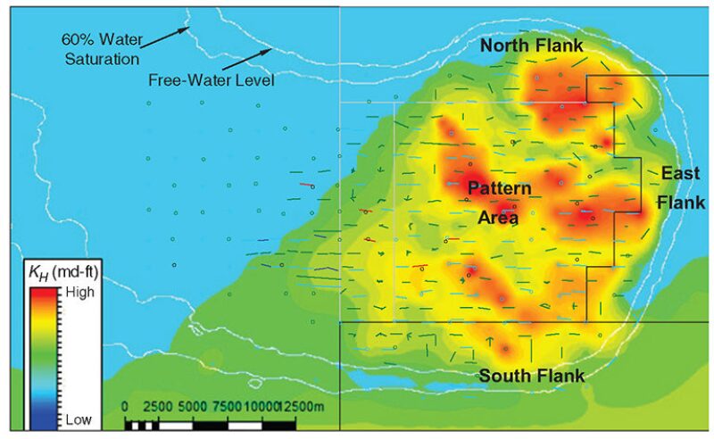
The development plan includes a comprehensive subsurface development scheme based on the available data and prediction tools. Development-plan optimization soon began as more data were being acquired and new reservoir models were built. This work is focused on development-plan optimization of two large flank areas of the largest reservoir in the subject field (south and east flanks in Fig. 1). These flank areas contain very large capillary transition zones that, although only a few hundred feet high, extend to several kilometers areally because of very low reservoir dip (1 to 2°) in a 150-ft-thick reservoir. Therefore, appropriate areal and layer placement of MRC wells in flank areas is a critical task that requires careful attention.

Reservoir Characterization and Modeling
A new geologic model was constructed by integrating extensive static and dynamic data. Careful attention was focused on reservoir characterization, including a new structural/fault framework, honoring of well tests and core data, a new rock-typing scheme, and an updated -water-saturation distribution with a variable free-water level based on additional well logs. A full relative permeability hysteresis model was deployed to appropriately initialize transition zones in flank areas. A full-field simulation model was then constructed and history matched by use of sector models with a domain-decomposition technique. A reservoir simulator was used with unstructured grids to honor faults in addition to using a fine-grid technique in oil zones and a coarse-grid technique in the aquifer. The reservoir contains several high-permeability streaks that were distributed stochastically in the static model and later adjusted during history match. The history-match modifications were recycled back to the static model, thereby keeping the static and dynamic models always synchronized. Sector models were extracted from the full-field model with suitable treatment of model boundaries that honored historical fluxes. The flux boundaries were fixed at target reservoir pressure in the prediction mode. Sensitivity studies were then conducted with areal and vertical placements of horizontal wells.
Well Placement in Flanks
Well placement in flanks requires careful attention. If areal well spacing is large, the injectors may not effectively provide pressure support. On the other hand, shorter well spacing can result in increased well counts, early water breakthrough, and higher water production; therefore, correct cost/benefit balance is necessary for optimal spacing. Furthermore, layer selection for horizontal-lateral placement for both injectors and producers is very important in ensuring maximum vertical sweep. The subject reservoir is approximately 150 ft thick, with upper zones having higher permeability compared with the lower ones. The injected water thus has a strong tendency to move in the upper zones and poses a significant challenge for efficient vertical sweep.
Appropriate integration of the subsurface plan with the surface plan is essential and requires significant effort. Some considerations that need to be taken into account for such optimization are
- Well spacing
- Rig usage and requirements
- Conversion of selected existing producers to injectors
- Horizontalization of existing vertical producers and injectors
- Selection of east or west direction and placement layer for horizontal lateral
- Performance of existing wells
- Injection-well capacities
- Integration of dual-producer conversion to injector with other reservoirs
- Island availability and drilling schedule
- Pressure-maintenance strategy
- Vertical placement of MRC wells in far flank areas
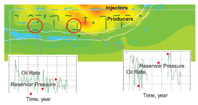
South-Flank Optimization. Fig. 2 shows existing wells in the South Flank. Historically, there were no injectors in this area and most of the pressure support was provided from the pattern area in the north at 1-km well spacing. Aquifer support is very weak because the reservoir permeability degrades when approaching the aquifer. Therefore, the initial development plan was based on 500-m areal well spacing, which was on the conservative side. The injectors and producers were arranged in a line drive with 3-km-long wells. To test injection support in the south flank, two existing producers were converted to injectors and the pressure response was monitored in two downdip producers 1 km away. Continued pressure monitoring showed a pressure increase in downdip producers within a period of 1 to 2 years. This new finding led to re-evaluation and optimization of the initial development plan.

Simulations were conducted with 1-km areal spacing while retaining as many existing wells as possible. Areal well locations were adjusted systematically to obtain the best areal sweep while taking the location of existing wells into consideration. The injectors were placed in lower reservoir zones consistent with the initial plan. The southernmost row of producers was placed in the upper zone, where oil saturation was sufficient to ensure adequate oil production.
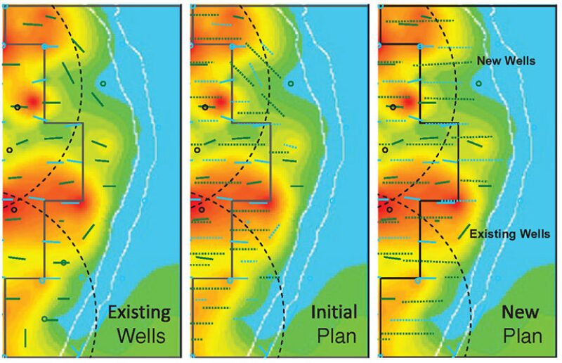
East-Flank Optimization. Existing well locations in the east flank are shown in Fig. 3. The figure shows that a number of existing wells are aligned with the flank boundary rather than with the east/west orientation seen in the rest of the field. The initial plan proposed several new wells also aligned with the flank boundary. Furthermore, well spacing in the east flank varied from place to place and some areas in the east flank were not fully covered. New reservoir models with more accurate characterization of water-saturation distribution in the east flank enabled further optimization possibilities, including alignment of wells with the historical east/west well orientation and initial flank development with 1-km well spacing.

If east/west well orientation were chosen, then the question was which layer to place the wells in. Drilling in the east direction areally places the wells perpendicular to the flank boundary directly heading into the aquifer. This is in contrast with the south-flank wells, where the well direction is parallel to the flank boundary. To address this issue, sensitivity studies were conducted for producer placements in various reservoir zones. As a result, the optimum well placement was found to be with the producer heel placed at the bottom zone and the toe in the upper zone while maintaining a reasonable standoff above the water/oil contact. Compared with placing the well in a certain stratigraphic zone, this kind of well placement offers longer reservoir contact in addition to better vertical sweep. Although the latter part of the well seems nearly horizontal, the toe of the producer is kept slightly lower to prevent water from slumping into the heel. The best vertical well placement for injectors was found to be in the lower zone, thus allowing more vertical sweep in the tighter bottom zone.
The new plan maintains the production plateau and significantly reduces water production because of optimal well placement above the water/oil contact.
Advantages of the New Plan
- Optimal areal well spacing creates significantly lower water production and adequate pressure support.
- Optimal vertical-well placement improves vertical sweep and significantly lowers water production.
- Achievement of target oil rate with fewer wells drilled means a lower cost.
- Addition of early production from flank areas helps in achieving target oil rate.
- Maintenance of production from existing wells means optimal use of existing facilities.
- Reduction of well count allows reallocation of rig time to other tasks.
- Development was extended to cover all flank areas.
- Alignment of all wells with 1-km pattern-area line drive facilitates drilling infill wells in the future.
- Optimal use of dual producers maintains production from other reservoirs.
This article, written by JPT Technology Editor Chris Carpenter, contains highlights of paper SPE 161591, “Development of Flank Areas in a Giant Carbonate Field With Optimal Placement of Horizontal Wells,” by Sameer Khan, SPE, Ali Al-Shabeeb, Zankar Jani, Yousef Azoug, Nguyen Minh, and Harshad Patel, SPE, Zakum Development Company, prepared for the 2012 Abu Dhabi International Petroleum Exhibition and Conference, Abu Dhabi, 11–14 November. The paper has not been peer reviewed.
