

The development of theoretical hydraulic-fracturing models started several decades ago, setting a basis for hydraulic‑fracture design, optimization, and diagnostics. As a reservoir stimulation technique, the problem of hydraulic fracturing in essence is the prediction of the geometric shape and dimensions (length, width, and height) of the growing fracture as a function of time. This mathematically translates to a set of nonlinear, integro-differential equations with moving boundaries, solved numerically over a number of time-steps (SPE 168600).
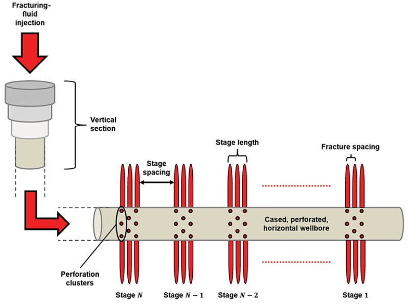
When it comes to multistage fracture treatments (Fig. 1), where many fractures are being “pumped” simultaneously within each stage, the problem’s complexity increases exponentially. The old adage of four inputs being necessary for optimal fracture design (reservoir permeabilities, in-situ stress distributions, a sound geological model, and a fluid-loss model in naturally fractured rocks) is no longer the case as multiple-fracture (multi‑frac) interactions and interference (intra-stage, intra-well, and inter-well) should also be incorporated (SPE 1210-0034‑JPT). Classic treatment‑design software, although convenient to use, struggle to predict multi‑frac growth geometries with sufficient certainty, leading to significant disparities between simulations and field observations.
Four real-world challenges associated with multifracture modeling from horizontal well operations are described below. Although each formation presents its own set of challenges rendering it necessary for operators to learn from experience, the development of computational techniques to facilitate the simulation of these common occurrences will yield more‑realistic models.
Nonsimultaneous Fracture Initiation Within a Stage
Fracture-propagation pressures are significantly smaller than fracture-initiation pressures (approximated by the recorded “formation-breakdown” pressures) in the same rock. Hence, earlier fracture initiation from one perforation provides a low-energy pathway for the fracturing fluid, which would “prefer” to enter an existing fracture and propagate it rather than initiating new fractures from nearby perforations.
Dominant (or Runaway) Fracture Creation
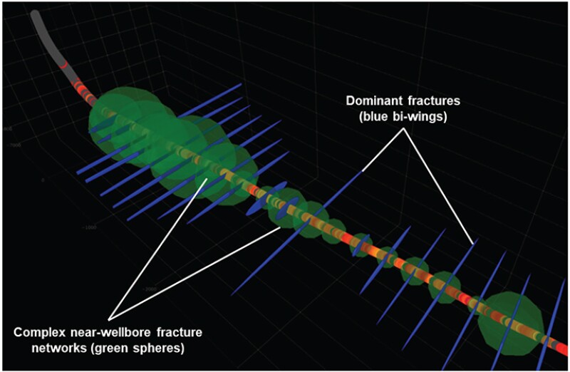
Dominant (or runaway) fractures are those whose growth is significantly larger compared to that of the other fractures. Laboratory-scale experiments where more than one fracture was pumped from a single fluid source displayed dominant fracture creation as a consistent observation (Michael). This observation qualitatively agrees with acoustic sensing data from the field-scale operations (Fig. 2). Dominant fractures end up receiving the entire fracturing fluid by the end of a stage (SPE 194334), while the remaining fractures cease propagating. The contribution of these few dominant fractures in the post-stimulation well productivity could be major.
Inactive Perforation Clusters
Fracturing fluid can bypass entire perforation clusters, initiating fractures from perforation clusters further downstream along the horizontal lateral (SPE 194334). This occurs both by inactive perforation clusters located between active clusters and by inactive perforation clusters located adjacent (upstream or downstream) of active clusters (Michael).
There are many possible causes of a perforation cluster failing to generate fractures, including nonsimultaneous fracture initiation and dominant fracture creation. Limited-entry techniques accomplished by varying perforation numbers and diameters (SPE-530-PA), later proposed for mitigating interference between simultaneously growing fractures from horizontal wells (“stress-shadowing”), can potentially be effective in eliminating inactive perforation clusters if specific patterns are detected.
Fracture Reorientation in the Near-Wellbore Region
The drilling of a well disturbs the surrounding stress field in a way that can make the plane of fracture initiation different from what is dictated by the far-field stress state. This causes fractures to terminate prematurely within the near‑wellbore vicinity (a few well diameters) or reorient themselves to align with the “proper” fracture plane as they propagate away from the near‑wellbore region (those that do are likely to become dominant fractures).
This generates complex near-wellbore fracture networks (Fig. 2), which induce fluid‑flow resistance, triggering completion and production‑related problems such as early screenouts and poor post-stimulation well productivity (SPE 173356).
Raising the Stakes in Hydraulic-Fracture Modeling
Engineering a successful hydraulic-fracture treatment involves several petroleum engineering subdisciplines, such as completion, production and reservoir engineering, a background in geomechanics and fluid dynamics, with good knowledge on the limits of the materials and equipment available. Incorporating economics enables optimizing the treatment design towards profit maximization.
Fracture geometry is arguably the most critical element of a treatment design, with a number of considerations made for influencing multifracture growth to optimize production and economics. Being able to confidently predict in advance the multifracture geometry generated in a treatment will enable “massification” of fracture operations with projects currently labeled unprofitable becoming profitable through cost reduction from lower capital expenditures.
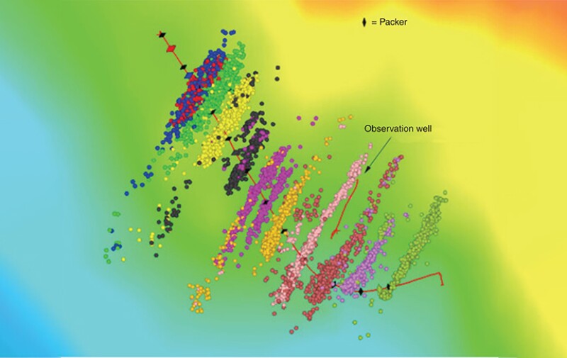
Post-stimulation productivity estimations along with the corresponding cash flows often assume individual fracture geometries that may bear no resemblance whatsoever to the actual multifracture growth resulting from a treatment. While users of standard industry software focus on downstream aspects when it comes to model validations and history-matching, such as production flow rates and volumes from a fractured well or pad, we cannot run away from multifracture geometry reliability questions for long. Post-fracture morphology data acquisitions using microseismic technologies (Fig. 3) can provide real-world multifracture geometry data necessary for tweaking computational simulators to improve their reliability, combining physics-based and data-driven modeling approaches.
For Further Reading
SPE 168600 Poroelastic and Poroplastic Modeling of Hydraulic Fracturing in Brittle and Ductile Formations by H. Wang, University of Houston; M. Marongiu, Economides Consultants Inc.; and M. Economides, University of Houston.
SPE 1210-0034-JPT Hydraulic Fracturing: The Fuss, the Facts, the Future by R. Beckwith, SPE J Pet Technol.
Hydraulic Fractures from Non-Uniform Perforation Cluster Spacing in Horizontal Wells: Laboratory Testing on Transparent Gelatin by A. Michael, Journal of Natural Gas Science and Engineering.
SPE 194334 Integrating DAS, Treatment Pressure Analysis and Video-Based Perforation Imaging To Evaluate Limited-Entry Treatment Effectiveness by D. Cramer and K. Friehauf, ConocoPhillips; and G. Roberts and J. Whittaker, EV.
C&J Energy, Seismos Combine Technologies To Evaluate Fractures as They Are Made by T. Jacobs, SPE J Pet Technol.
White Paper: Maximizing Production by Optimizing Near-Field Connectivity by Seismos, SPE J Pet Technol.
SPE-530-PA A New Development in Completion Methods—The Limited-Entry Technique by K.W. Lagrone and J.W. Rasmussen, Shell Oil Co.
SPE 173356 Calculation and Implications of Breakdown Pressures in Directional Wellbore Stimulation by J.L. Miskimins, Barree & Associates.
SPE 148780 The Advantage of Incorporating Microseismic Data Into Fracture Models by J. Shaffner and A. Cheng, Pinnacle; and S. Simms, E. Keyser, and M. Yu, Encana Corp.

Andreas Michael, SPE, is the advisor of SPE’s The Way Ahead. He is a postdoctoral fellow at Colorado School of Mines’ Civil and Environmental Engineering Department, doing research on underground tunnels. Michael holds bachelor’s and master’s degrees from The University of Texas at Austin and a doctorate from Louisiana State University (LSU), all in petroleum engineering. His PhD dissertation on “Fluid-Driven Fracture Initiation from Oil and Gas Wells Considering Lifetime Stresses” received LSU’s Distinguished Dissertation of the Year Award for STEM in 2020. He has published six journal articles, 22 conference papers, and 16 magazine articles. At the 2019 SPE Annual Technical Conference and Exhibition held in Calgary, he captained LSU’s PetroBowl team to win the championship and placed second in the PhD division of the International Student Paper Contest.