There are considerable benefits to conducting rigless subsea well intervention from specialized monohull vessels. Two case studies provide an overview of operations on subsea wells, from intervening through the production tree (XT) to XT change-out and well-plug-and-abandonment (P&A)/wellhead-removal operations.
Overview of Rigless and Riserless Light Well-Intervention (RLWI) Techniques
Rigless and RLWI activities have been carried out for more than 25 years across the North Sea. The purpose of the following case studies is to demonstrate that with effective project management (planning, developing, execution, and close-out), the use of RLWI is a flexible and extremely cost-effective method that operators can use for a single well or across a number (a campaign) of subsea wells, irrespective of subsea-tree type or close proximity.
In order to conduct in-hole subsea-well operations without the use of a traditional mobile offshore drilling unit, three pieces of critical equipment (along with a trained and competent crew) are required:
- A dynamically positioned vessel of sufficient size and capability to accommodate the equipment and personnel required
- A derrick or tower with heave compensation to deploy and recover equipment
- A subsea-intervention lubricator (SIL) to facilitate well control and well access
SIL
The SIL provides access to the wellbore. It is interfaced with the well-specific re-entry interface (usually a tree-running tool) and is run from the vessel as a standalone unit on wire, latched onto the tree, tested, and then left free-standing on the well without riser back to surface. It is controlled by a single umbilical with full emergency-shutdown and emergency-quick-disconnect functionality and redundancy.
Wireline tools are run into the SIL through the water column, followed by the open-water latch system (OWLS) that then effects a seal around the wire upon latching into the top of the SIL. Once latched, the riser is flushed to the glycol mix being used, whereupon the well is opened, the toolcatcher is released, and the tools are run in hole in the normal manner with full compensation.
The SIL subsea system consists of a lower riser assembly housing the well-control blowout preventers (BOPs) and electrohydraulic control modules. This is connected by an emergency-disconnect package to the upper riser assembly (URA), which comprises the main umbilical interface, further control manifolds, the electric-line subsea grease-injection system, and contingency wireline BOPs. Integral to the URA is the lubricator (riser) section, which houses the downhole tooling before deployment, and the upper-upper riser assembly, which contains a wireline-cutting ball valve and the hydraulic latch for the OWLS.
Should an emergency situation drive an emergency quick disconnect, the umbilical and guidewires (if run) disconnect, all the in-line and wellbore wetted valves close, and the system is left free-standing on the subsea tree with well-control integrity fully maintained.
Case Study 1: North Sea Campaign
Between December 2011 and February 2012, the RLWI vessel MSV Seawell was mobilized by a major North Sea operator to perform a series of light well-intervention (LWI) operations across a number of UK continental shelf North Sea fields during a single campaign. The versatility of the LWI vessel was demonstrated with a varied workscope, allowing the campaign to be performed efficiently because of the faster transit speed of a monohull vessel between locations, removing the need for a supply vessel and minimizing helicopter requirements.
Well-intervention operations were conducted on seven wells across six fields of varying water depths (90 to 141 m), with a campaign lasting 68 days.
The North Sea campaign was initially planned to use a 5⅛-in. (through-bore internal diameter) SIL for conventional XT access. However, during the planning phase, an additional well developed integrity issues that required immediate intervention to secure well integrity. This additional well was outfitted with a horizontal XT with a different configuration from conventional XTs; this new XT had crown/tubing hanger plugs that need removing by use of an SIL before undertaking LWI. These plugs are generally in excess of 7 in. in circumference, necessitating a larger-internal-diameter-bore SIL.
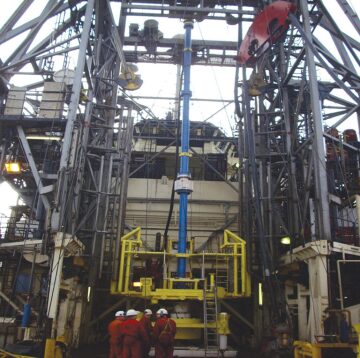
In order to address this issue, another contractor-owned SIL, a 71/16-in. package, was mobilized and used on the well in question. The early identification of this issue, through good communication and planning between the operator and contractor, allowed the 71/16-in. SIL (Fig. 1) to be mobilized rapidly from the contractor’s Asia Pacific operations base and flown, by charter, from Australia to the UK to meet the critical operational time frame.

Operational Challenges. On discovering the integrity issues with the horizontal XT in question, it was necessary to conduct a site visit to the tree vendor’s premises to get an overview of a tree that was similar to the one installed. Because the workscope required diver intervention, and with restricted access, a considerable amount of prejob planning was conducted.
The fabrication of components to aid repair of the horizontal XT was initiated, and these were built in a short time to meet the operational schedule. The equipment that was required to interface the SIL and client tree-running tool (TRT) was sourced through several collaborating operators and integrated/tested.
The SIL system was dispatched from southeast Asia on 15 December and arrived in the UK on 17 December. The new SIL system was sent to the MSV Seawell on 4 January; the old system was demobilized, and the vessel sailed 3 days later. The workscope was undertaken offshore and completed within 2 weeks with a successful well suspension, and full well integrity was reinstated.
A total turnaround of 50 days saw the system fly from one side of the world to the other to carry out a high-profile integrity-issue repair project, demonstrating the benefits and flexibility of conducting LWI operations over a short time scale.
Operational Workscope.
- LWI (well maintenance and production enhancement) on three wells
- P&A (decommissioning operations) on three wells
- One scale squeeze (pumping inhibitors and treatment; production enhancement)
The following workscopes were supported with saturation diving operations, allowing diver inspections and manifold maintenance to take place simultaneously:
Multiservice Campaign.
- Total electric-line runs: two
- Total slickline runs: 15
- Pumping
- Abrasive wellhead severance
- Remotely operated vehicle and saturation diving
Case Study 2: Equatorial Guinea Campaign
The LWI vessel Well Enhancer sailed from the UK to perform operations in Equatorial Guinea in January of 2012. The planning for this operation was conducted by the operator in Houston and the LWI contractor in Aberdeen, with the ultimate operations to be managed locally from Equatorial Guinea.
The campaign was initially planned for eight wells (later reduced to seven) in varying water depths (120 to 471 m) with a workscope of well-integrity-type operations and a subsea-tree change-out. The campaign was performed in 66 days and was planned with three phases such that only one port call was required during the campaign.
First LWI From a Monohull Vessel in Africa. The Well Enhancer sailed from the UK to Las Palmas, Spain, with the vast majority of the key equipment onboard. From there, and upon customs clearance in Malabo, the vessel mobilized additional equipment and well-servicing personnel and sailed to the field to commence operations.
Other than demobilization, across the campaign there was only one further port call (in Malabo) to mobilize the new/replacement XT and its TRT.
The campaign planning started approximately 6 months before the operation mobilization. A dedicated project engineer was assigned to work with the client (their support staff and wells and subsea superintendents) at their corporate office in Houston.
The project engineers also had to be the focal point in planning and coordinating between key locations (Houston, Aberdeen, and Malabo). Improved operational sequences were developed during the planning phase to streamline the logistical and operational periods of the campaign and to identify particularly long lead items and equipment such as tree-cap-retrieval tools (TCRTs) and tree crossovers.
In July, additional project engineers, who would later supervise from Malabo or onboard the Well Enhancer, were assigned to the client office in Houston for a 4-month period. Once the procedures were drafted, the project team and all third parties attended a 1-week planning session in Aberdeen to finalize the program and the safety-management-system bridging documents, and to confirm the status of project equipment.
As per standard contractor procedures, a 1-day hazard-identification meeting was also attended by all parties before the mobilization of the equipment, to allow personnel to identify and counter possible operational risks during the campaign.
Operational Challenges. The main technical challenge was based around the interfacing of subsea equipment (XT/TRT/TCRT all in different regions). The new XT was in Houston, TRTs (two types) and TCRTs were in Malabo, and the SIL package was operational in the North Sea region.
The issues were resolved by placing a project engineer in the client office in Houston, working alongside subsea-equipment suppliers to manage and coordinate the interface of the key subsea equipment. Weekly conference calls were held between Malabo, Aberdeen, and Houston.
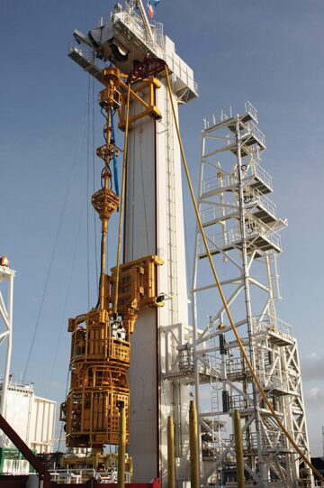
Once the crossovers (which interface between the TRT and the SIL) were manufactured, the TRTs were shipped from Africa to Aberdeen and the crossovers were installed and tested before mobilization from Aberdeen. The TRTs then remained in Aberdeen until the mobilization, allowing for the interfacing of all the equipment onboard in Aberdeen and complete testing before sailing to Equatorial Guinea. The final stack is shown in Fig. 2.

Operational Workscope.
- Installation of barriers in production/annulus bore for two wells
- Subsea-tree replacement and production reinstatement for one well
- Gas lift valve change-out for four wells (increased rate of production)
Multiservice Campaign.
- Total slickline runs: 52
- Gas lift valves replaced: 15
- Total electric-line runs: 0 (electric line was a contingency and was ultimately not required)
- Pumping
- Remotely operated vehicle
This article, written by JPT Technology Editor Chris Carpenter, contains highlights of paper OTC 24065, “Rigless-Intervention Case Studies: UK and Africa,” by Oliver Willis and Phillip Bosworth, Helix Energy Solutions Group, prepared for the 2013 Offshore Technology Conference, Houston, 6–9 May. The paper has not been peer reviewed. Copyright 2013 Offshore Technology Conference. Reproduced by permission.
