Drillers live with a worrisome question: How much fluid is actually flowing out of the well compared to what flowed in?
A growing rise in the fluid flowing out can signal a dangerous gas influx, increasing the volume of the outflow.
Accurate measures are needed to create a condition-monitoring system allowing a driller to more accurately assess what is coming out and to distinguish changes that are warnings signs from routine fluctuations during drilling, such as turning mud pumps off and on.
Eric Cayeux, chief scientist for the Norwegian Research Centre (NORCE), is working on filling a need for a “quantitative” measurement of the flow rate out of the well that is not influenced by mud mixing and treatment activities.”
The widely used tool he wants to replace is a paddle that moves up and down based on the flow rate—seemingly a low bar to clear.
Cayeux describes paddles as “a very crude instrument which can only be used to give a gross indication of the flow rate” in a paper about his work at NORCE (SPE 199661).
However, sometimes the indications are misleading. Paddles can get stuck when mud clogs the hinges. A change in the level may be due to a change in fluid properties rather than flow rate.
Fluid levels in return tanks are a measurable indication of the difference between flow in and out, but fluid transfers among mud pits can complicate the calculations, as can measuring fluid levels on moving offshore platforms.
On the input side, counting pump strokes offers a measure of how much fluid is pumped into the well, but the volume depends on pump efficiency, which drilling experts say varies.
There is one direct measurement tool for flow that offers quantitative results—a Coriolis mass flowmeter. It can directly measure the flow, but must be fully filled to work and requires a location below the flowline. Such a location can be hard to find, and particle buildups inside the flowmeter can lead to misleading results.
Cayeux is working on a device that he thinks can fit onto the crowded decks of a drilling rig, is more durable, and is able to flush out the solids, making it more reliable.
The NORCE design is based on the same scientific principle as the Coriolis meter but doesn’t look like one inside. It has also proved its mettle in a tougher line of work—measuring fine-grained sand and cement in industrial facilities.
The inspiration is “rotating measurement wheels” used to measure sand and powder flows in industrial facilities.
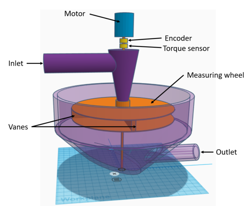
The wheel inside this device looks a bit like paddle wheels once used to drive steamboats. It has four blades mounted at 90-degree angles—imagine a fan with four blades sandwiched between two solid, round plates of steel.
In this case, fluid flows down from the top of the device into the center of the wheel which is rapidly turned by an electric motor at a steady rate.
“The flowable material exerts a force on the vanes. This force results in a torque on the axle of the motor shaft that drives the measuring wheel,” Cayeux said. The degree of torque depends on the flow rate of the material as centrifugal forces push it out toward the open sides of the wheel. The formula used to convert that torque change into a volume measure is based on the fact that the flow is subject to the Coriolis force.
As the wheel ejects the fluid and particles off the walls of the device, the sound of that collision offers a second data point. The noise can be used to estimate the number of particles and their mass distribution in the fluid.
From there, the fluid and particles flow down the walls of the flowmeter and out. This is supposed to prevent the particle buildup that causes traditional Coriolis flowmeters to malfunction.
“Because of the constantly rotating measuring wheel, there is no chance that solid particles settle in the instrument,” the paper said.
Other sensors can be added to extract more information.
The motion separates out gas, allowing it to be analyzed. Also, a small part of the outflow can be measured in a densometer to determine its mass density. Yes, that added option would require a Coriolis flowmeter, but Cayeux said small ones are more reliable than big ones and cost only about $5,000.
Cayeux is now recruiting members for a joint industry project to test a larger-scale prototype. He expects the final design will be about 2 m tall and can handle 5,000 L/min. The parts required are neither costly nor hard to find.
"All of those elements are very standard equipment and do not require special electronic expertise. So, I would guess that the cost of fabrication should be quite acceptable,” he said.
Interested in more drilling technology? Visit our upcoming events:
- IADC/SPE Asia Pacific Drilling Technology Conference, 1-2 September, 2020
- SPE/IADC Middle East Drilling Technology Conference, 15-17 September, 2020
- SPE/IADC International Drilling Conference and Exhibition , 9-11 March, 2021