

This work describes the positive results experienced when a self-diverting acid system based on a viscoelastic-surfactant (VES) technology was introduced for carbonate-reservoir stimulation offshore Brazil. The self-diverting (SD) VES (SD-VES) promotes viscosity development when the acid comes in contact with the carbonate formation. Since the SD-VES was introduced in this environment in 2009, more than 40 wells have been treated with the system.
Introduction
Matrix acidizing is frequently used to stimulate carbonate reservoirs offshore Brazil. In these treatments, a proper diversion technique is required to direct the treatment fluid to lower-permeability or more-damaged zones and ensure the treatment of the entire production interval. The chemicals developed and used as diverting agents include polymer gels, foams, oil-soluble resins, and rock salt, among others. Offshore Brazil, polymer-based systems have been applied successfully. Such systems are easier to handle than particulates, and diversion is achieved through the formation of natural resistance to viscous flow. Generally, the treatment is divided into three phases: a regular 15-wt% hydrochloric acid (HCl) is pumped first, followed by a gelled 15-wt% HCl, and finally by a pill of in-situ-crosslinked gelled 3-wt% HCl. In most cases, several stages are pumped, repeating the three phases in order to cover the entire interval.
Despite the success experienced with polymer systems, concerns about the potential damage to the formation provided an impetus for the successful introduction of a viscoelastic-acid system offshore Brazil.
VES Diverting Agent
Surfactant-based acids constitute systems called viscoelastic systems. These systems have been studied and applied extensively over the last decade to overcome potential disadvantages of in-situ-crosslinked polymer-based systems. Unlike conventional crosslinked acids, VES fluids do not require a metallic crosslinker and were used successfully in both matrix stimulation and acid fracturing.
The SD-VES introduced in Brazil in 2009 is characterized by a single fluid used to stimulate and divert. (For a discussion of the diversion mechanism, please see the complete paper.) In most applications, the system is bullheaded as the main acid fluid, and no other fluids are intercalated with the system. This approach has been applied in several wells, with very good results.
SD-VES Characteristics. The rheological properties of the SD-VES, when spent with calcium carbonate (CaCO3), indicate slight influence of the initial acid concentration. Laboratory tests indicated that higher initial HCl concentration (equal to or higher than 20-wt% HCl) tends to create a viscosity spike when spent to 10- to 15-wt% HCl, while lower initial HCl concentration tends to result in a viscosity spike when spent to lower concentrations. The SD-VES used offshore Brazil generally is pumped in acid concentrations ranging from 15- to 17-wt% HCl; laboratory tests indicate that the viscosity spike occurs at a concentration of 5- to 10-wt% HCl. Temperature plays an important role in acid viscosity and is directly affected by the pH.
Regarding the shear-rate effect on the apparent viscosity, a power-law relationship was observed, with the viscosity decreasing with the shear rate. This behavior is important in minimizing friction losses during placement, when the fluid is submitted to higher shear rate, resulting in lower viscosity. The shear rate decreases significantly as the acid enters into the formation. The injected acid will continue to gain viscosity as it spends, to achieve a maximum value as the formation’s natural resistance causes the fluid to approach a static state.
For a discussion of the results of coreflood tests, please see the complete paper.
Acid Placement and Well Completion
For acid placement, distinct techniques have been applied, depending on the well objective. The main placement techniques applied offshore Brazil are summarized as follows:
1. For treatment for zones not isolated by a packer, two approaches have been used:
a. Use coiled tubing to place a small volume of acid in the lower part of the perforations, creating a zone of preferential injectivity. The main treatment is bullheaded, generally using the SD-VES. This procedure has the main objective of forcing the acid to travel through the entire perforated zone (Fig. 1).
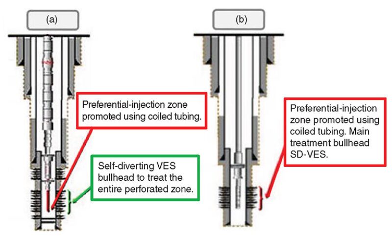
b. Run diverting wash pipes to perforate the interval and place a small volume of acid to create initial injectivity. Afterward, the SD-VES is bullheaded to the formation and constitutes the main treatment (Fig. 1, Case b).
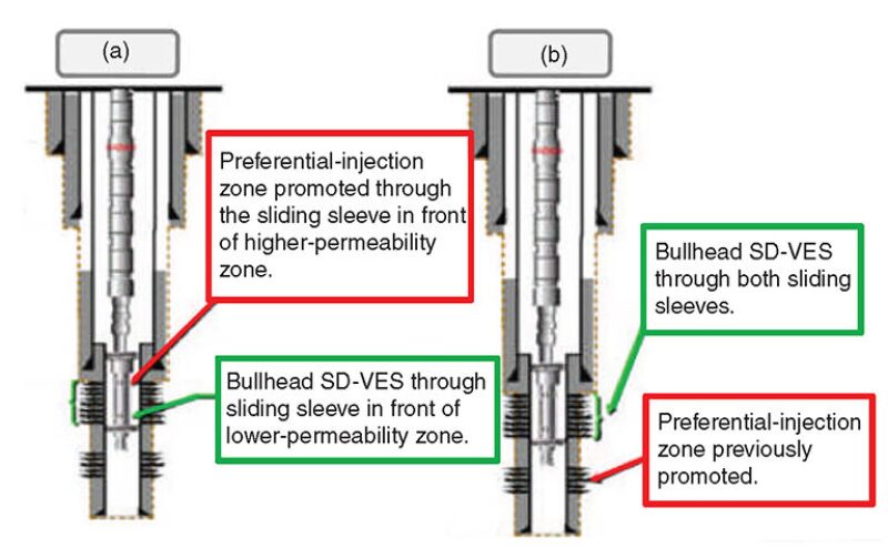
2. For treatment for zones isolated by a packer, in the present completion approach, the well is equipped with a sliding sleeve at the bottom of the perforations and another one at the top of the interval. The treatment is performed using the following approaches:
a. The same technique described in 1a is used.
b. For a well completed in two zones, the treatment can also be bullheaded without using coiled tubing, keeping both sliding sleeves open. In this case, a lower zone below the packers has already been treated and is used as a preferential-injection zone to direct the preflush acid to the bottom of the packed interval. When the main acid reaches the upper interval, the lower zone is mechanically isolated. Generally, the SD-VES is used as the main acid (Fig. 2, Case b).
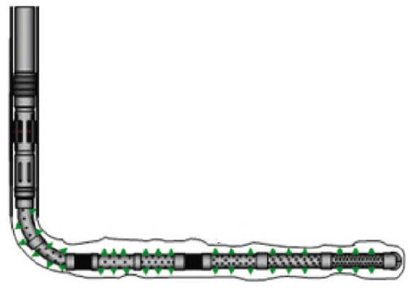
3. For horizontal wells, two approaches have been used:
a. A combination of a diverting liner and the creation of a preferential-injection zone as in 1a. After pumping a small volume of acid through coiled tubing, the main treatment is performed, generally bullheading the SD-VES (Fig. 3).
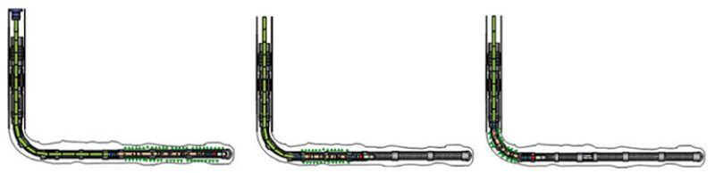
b. A combination of a conventional perforated liner and diverting wash pipes placed in front of the treated zone is used. The main treatment is usually performed bullheading the SD-VES (Fig. 4).
Case Histories
Here, two of the three case histories presented in the complete paper are detailed, although all three cases experienced positive results with the use of SD-VES.
Well B. The placement approach used to treat Well B is the same presented in 1a in the preceding section. The well was a vertical oil producer completed with 7-in. perforated liner. The formation was a carbonate located in a presalt play with permeability ranging from 1 to 20 md and porosity of 14%. The well temperature was 144°F.
Treatment Strategy. Coiled tubing was used to treat the final portion of the perforated interval (16,272 to 16,354 ft). The main goal of this first treatment was to create a zone of preferential injectivity, forcing the later bullheaded acid into the bottom perforations. The coiled tubing was equipped with a special rotating tool to jet the perforations better. A total volume of 140 bbl of regular 15-wt% HCl was pumped and injected into the formation.
After the coiled-tubing treatment, a total of 2,000 bbl of SD-VES (15-wt% HCl with 6 vol% of viscoelastic surfactant) was pumped to treat the entire perforated interval. While bullheading, the pumping rate was increased in steps to 15 bbl/min. After pumping 200 bbl of the SD-VES, the operations personnel began to launch water-soluble perforation ball sealers. These organic-based balls slowly dissolve in any aqueous fluid. A total of 1,800 ball sealers was distributed during the treatment.
Post-Treatment Results. After the treatment, the skin experienced a significant reduction, becoming a negative number (indicative of good stimulation). The permeability and, consequently, the conductivity also presented significant improvement. The production index was increased almost tenfold, and the damage ratio was reduced to a number less than unity.
The temperature log presented a reduction in the upper zone, indicating fluid production. The oil-rate curve confirms the main production contribution from the upper, higher-permeability zone (16,072 to 16,232 ft). The production from the lower zone (16,232 to 16,367 ft) was almost insignificant. The high permeability contrast between the zones probably was responsible for the lower zone’s poor response to treatment. For Well B, the placement technique presented in 1b in the Acid Placement and Well Completion section could represent a better approach to direct the acid to the lower zone.
In general terms, the acidizing was successful, as confirmed by a 6-month production test that indicates production of 12,578 B/D (2000 m3/d) with a gas/oil ratio of approximately 250. No water production was observed during the test (water cut less than 0.1%).
Well C. The placement approach used to treat Well C is the same presented in 1a in the Acid Placement and Well Completion section. Well C was an oil-producing vertical well completed with 7-in. perforated liner. The formation was a presalt carbonate with large heterogeneity, presenting minerals as calcite (predominant), dolomite (20 to 30%), and some silicates. The permeability distribution is also heterogeneous, with the lower zone having higher values. The well temperature was 255°F, so the corrosion-inhibitor concentration in the SD-VES was increased from 1 to 2 vol%.
Treatment Strategy. Coiled tubing was used to treat the final portion of the perforated interval (14,694 to 14,924 ft). The main goal of this first treatment was to create a zone of preferential injectivity, forcing the subsequent bullheaded acid into the bottom perforations. The coiled tubing was equipped with a special rotating tool to jet the perforations better. A total volume of 90 bbl of regular 15-wt% HCl and 100 bbl of a special gelled acid (17-wt% HCl with 2 vol% of gelling agent) was pumped and injected into the formation while the coiled tubing was moved up and down in front of the treated interval. During the bullheading treatment, a total volume of 2,450 bbl of SD-VES (15-wt% HCl with 6 vol% of VES) was pumped to treat the entire perforated interval. During bullheading, the pumping rate was increased in steps to 20 bbl/min. After pumping 490 bbl of the SD-VES, operations personnel began to launch perforation ball sealers. A total of 1,400 ball sealers was distributed during the treatment.
Post-Treatment Results. The skin for Well C obtained from a production test was determined as -3.4. A resistivity log run after the acid treatment indicates water presence below 14,914 ft. A water cut of 1% was determined, and no gas presence was observed from optical logs. The temperature log indicates production contribution from the entire perforated interval.
The production-logging tool run after the acid treatment indicates production through the lower 508 ft of perforations, which corresponds to 77.5% of the perforated interval. It is an impressive result, considering the high permeability contrast presented by the perforated interval.
Considering the perforation length and high permeability heterogeneity presented by the reservoir, the operator classified the treatment as successful. As a strategy for future treatments in similar scenarios (wells where lower zones have much higher permeability than upper zones), pumping the initial barrels of the bullheaded acid at lower rate could improve the treatment distribution, giving the acid more contact time with the upper zone.
This article, written by JPT Technology Editor Chris Carpenter, contains highlights of paper SPE 165089, “Self-Diverting Acid for Effective Carbonate Stimulation Offshore Brazil: A Successful History,” by A.T. Jardim Neto, C.A.M. Silva, R.S. Torres, R.L. Farias, F.G.M. Prata, and L.A.M. Souza, Baker Hughes, and A.Z.I. Pereira, A. Calderon, and E.F. Sandes, Petrobras, prepared for the 2013 SPE European Formation Damage Conference and Exhibition, Noordwijk, the Netherlands, 5–7 June. The paper has not been peer reviewed.