This paper focuses on the applicability of subsea-processing technology (SPT) using multiphase pumps (MPPs) to develop marginal fields commercially. A technology selection consisted of a comparison of performances of several SPTs for effective development of marginal fields and was evaluated further with an analytical hierarchical process, resulting in the most effective innovative SPT for marginal-field development. The findings of this process were validated further in their applications to real fields, reflected in specific field-case simulation studies.
Introduction
Most of the world’s exploration-and-production companies have a significant number of unconventional and remote fields in their portfolios. Recent industrial effort has been focused on the accelerated development of SPT. One of the innovative solutions is the handling and treatment of produced oil and gas at or below the seabed for transport to topside facilities, to mitigate flow-assurance issues.
Some of the notable benefits of subsea processing include mitigation of hydrate formation and management of pressure-related issues resulting from the production of heavy oil, increase in wellhead pressure, and increased hydrocarbon production from fields with low pressure profiles. In ultradeepwater and deepwater fields, subsea processing is the most effective solution because such fields are beyond human intervention (divers), and it is used to boost hydrocarbon production from green fields or brownfields, reducing production cost and the need for topside processing.
This paper explores subsea processing in the development of offshore fields. From the concept selection, an optimal or near-optimal solution of SPT was then applied to an offshore-field development. The application of the optimal solution is simulated with a transient-multiphase-flow dynamic-model program, and the production profiles obtained from the simulation are compared with the reservoir’s production profile. The present paper considers results presented on subsea MPPs as a possible solution to develop marginal offshore fields commercially.
Results and Analysis of Field-Case Study
The simulation covers an 8-year production period simulated over two isolated cases (see the complete paper for discussions of four such cases) with varying water cuts and productivity index (PI). This simulation compared the most-innovative and -effective SPT found through analysis, which is multiphase pumping. The base case is modeled in a transient-multiphase-flow program without any form of subsea processing or gas or water injection. Field A is a typical example, and the current production profile uses an electrical submersible pump (ESP) to boost production; however, this is not modeled here because of the difficulty in handling free gas at suction conditions, because this reduces the efficiency of the pump and creates difficulty in modeling an advanced gas handler or gas separator for an ESP in the transient-multiphase-flow program.
Hence, for each of the cases in the 8-year period, we ran concurrent simulations for different field-development profiles. The field-development profiles were simulated for two production cases:
- Case 1 produces fields without subsea processing (base case without SPT).
- Case 2 produces fields with subsea processing using multiphase pumping.
Field A. The field is located in the North Sea, at a water depth of more than 180 m and a seabed temperature of 4°C. A 26 000-m length of pipeline at an uneven seabed is expected to create slugs in the flowline. The well that was considered was a deviated well with a vertical depth of 1848 m from the seabed and a horizontal distance of 800 m from the wellhead. This is a high-pressure field, with reservoir pressure in excess of 200 bar and temperature in excess of 70°C. Production is through water injection, tied back to a floating production, storage, and offloading vessel.
Field B is discussed in detail in the complete paper. Two field-case studies from Field A will be outlined here; please see the complete paper for the results of two field-case studies from Field B.
We assumed the source at the inlet to be a pressure node. The model for simulation contained one well from the reservoir. It consists of a wellhead and manifold. The wellhead and manifold are represented by open nodes allowing mass flow through them. The multiphase pump was modeled using a Framo pump, a built-in MPP in the transient-multiphase-flow program. The simulation is concluded at the riser base of the pipeline, with a pressure node used to simulate the riser base. This simulation does not cover produced-water reinjection. We assumed a constant heat-transfer rate for the media through which the fluid passes, through the well and seabed conditions. The water cut increases from an initial rate of 0% to 86% at varying years, with varying PIs. The well positive flow is modeled by use of a linear equation. At the reservoir level, we assume the fluid to be in a single phase.
Each simulation was modeled for a 12-hour period to allow for a stable system and avoid unpredictable conditions caused by startup operations.
Analysis of Field A, Case 1 (Base Case)
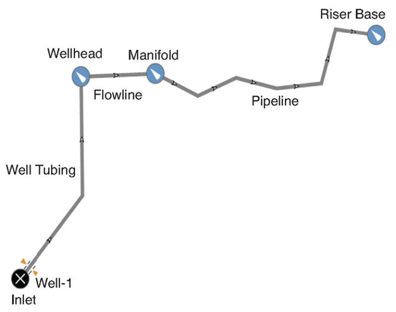
The transient-multiphase-flow model for Case 1 of Field A is presented in Fig. 1.

Model Description. The well is a deviated well at a depth of more than 1800 m below seabed, a temperature of 70°C, and pressure of more than 200 bar. The well tubing was modeled with steel and formation (essentially rock). The well tubing has a nominal diameter of 5.5 in. and wall thickness of 0.304 in. The overall heat-transfer coefficient is taken to be 12.5 W/m2·°C. The wellhead is taken as an open node, the dimension of which is computed by a transient-multiphase-flow dynamic model program in the simulation. The pipeline is neither buried nor trenched on the seabed. The total pipeline length from wellhead to riser base is in excess of 27 km. The pipeline depth undulates between 145 and 180 m below water surface. Because of this undulation, severe slugging occurred at some sections of the pipeline.
The well was simulated using a pressure node because there is no need to enter flow rate of fluid. The output (the riser base) is also simulated using a pressure node, with the arrival temperature and pressure defined. The transient-multiphase-flow program modeled the flow from the well to the riser base, thereby computing the flow rate, flow profile amount, and types of fluids produced. This base-case simulation was run for a period of 12 hours for each set of varying criteria.
Results. A drop of approximately 50% in production-flow rate is observed between Year 1 and Year 8 with the application of subsea processing (please see the complete paper for further details and supporting plots).
However, the profile plots for Year 1 and Year 3 pressure variations showed that slugging was not predominant in the system. Plots of pressure from Year 1 through Year 3 showed a decrease in pressure. Increasing the water content of Case 1 led to an increase in slugging frequency within the pipeline, high pressure variations, and changes in flow rate. Sensitivity analysis was carried out by varying both the PI and the water cut. Results from the analysis showed that slugging developed at a PI of approximately 79 and low water cut (above 55%) for Case 1. This led to pressure differentials of approximately 15 bar within the pipeline and flow-rate variation of approximately 7000 m3/d. The slug regime is termed hydrodynamically induced slugging because slugs result from large variations in the number of waves at the gas/liquid interface during stratified flow.
A continuous increase in water cut and reduction in PI take place at Year 8 before the slug regime leads to backpressure, or negative pressure, of up to 17 bar in the pipeline. This leads to an uneven flow rate in the system, with a reduction in production and with system instabilities and flow-assurance issues.
Observed clearly from the slugging and production-flow-rate analysis, the well in Field A might prove technically not unfeasible and uneconomical to produce or continue production, especially from Year 5. Consequently, the field cannot be exploited effectively without some application of subsea processing.
Analysis of Field A, Case 2
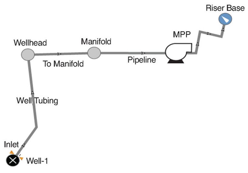
The transient-multiphase-flow model for Case 2 of Field A is presented in Fig. 2.

Model Description. The reservoir, flowline, and pipeline characteristics are similar to those of Case 1 (base case). This model incorporates an MPP along the pipeline close to the manifold.
Results. Year 1 of simulation is a system with a fairly high flow rate of approximately 4060 m3/d close to the riser base of the pipeline, which is explained by the low water cut and high PI from the reservoir. By Year 3, there is a steep fall in production rate. The production rate or flow rate falls to approximately 2300 m3/d. This can be explained by the rapid increase in water cut of the system from 0% to 47%, the drop in PI from 16.8 to 7.3, and the inception of slugs. Year 5 shows a slight increase in flow rate to approximately 2500 m3/d. This is explained by the increase in PI over the previous year. Year 8 of simulation shows an increase of flow rate to approximately 2700 m3/d as a result of a high PI of approximately 86. This is the second-highest flow rate on the graph and is explained by the multiphase pump and reduction in slugging in the system.
During Year 1 of simulation, there is a slight variation in pressure (0.2 bar) and a flow-rate variation (300 m3/d). These variations are a result of startup of the multiphase pumping, pipeline topography with regions of undulation, and position of the MPP on the pipeline. All these result in regions of instability along the pipeline. This variation in pressure completely evens out after approximately 2 to 3 hours of operation of the system. By Year 3 of simulation, there is a slight increase in pressure variation of the system in the region of 0.4 bar and variations in flow rates of 2000 m3/d. This slight variation evens out after approximately 2 to 3 hours.
The fifth year of simulation does not show any remarkable variation in flow rate. This can be explained as a result of the high PI of this year. Year 8 of simulation results in a higher magnitude of variations in pressure compared with the previous years for this case. There is an onset of slugging caused by the factors mentioned previously, in addition to high water cut of the reservoir. Year 8 is characterized by pressure variations in the region of 0.6 bar and flow-rate variations in the region of 11 000 m3/d. After 2 to 3 hours of operation, this fluctuation evens out to give a fairly stable flow.
For a summary of all field-case studies, including a cost analysis, please see the complete paper.
Conclusions
The analysis shows that multiphase pumping, in terms of performance, offers a relatively high value for shallow marginal fields. This results in an even production profile, with variable increase in production, thereby reducing flow-assurance issues and extending the field’s productive life. The analysis shows that this also increases the life of the field’s production facilities and is best implemented at a late stage of the field’s life or when the water cut is greater than 70%. MPPs should be kept as close to the wellhead as possible to prevent separation of fluid phases. Multiphase pumping is also environmentally friendly. An increase in reliability and availability of multiphase-pumping technology makes it an excellent choice for application to marginal-field developments.
This article, written by JPT Technology Editor Chris Carpenter, contains highlights of paper SPE 165587, “Reassessment of Multiphase Pumps in Field-Case Studies for Marginal Deepwater Field Developments,” by N. Abili, F. Kara, and I.J. Ohanyere, Cranfield University. This paper was peer reviewed and published in the February 2014 SPE Oil & Gas Facilities magazine, p. 56.
