
The gas-producing carbonate zones of the Ghawar field in eastern Saudi Arabia have been affected by extensive iron sulfide (FeS) scale deposition, reducing overall gas production and increasing risks during well interventions. Previous remediation attempts used workover rigs, which can be costly because of the time necessary for workovers and lost production. Hydrogen sulfide (H2S) levels (2 to 5%) in the reservoir also contribute to higher costs and risks with the use of workover rigs. H2S in the reservoir poses a safety concern with the returns at surface and a concern with potential corrosion of the coiled tubing (CT) and completion. Therefore, the safest and most economical method was deemed to be mechanical descaling with CT.
Introduction
Two wells were descaled mechanically by use of CT. Each well involved four major challenges: low reservoir pressure, higher reservoir temperature, horizontal openhole completion, and high-specific-gravity (3.7 to 4.3) scale. The low reservoir pressure required pay-zone isolation to enable circulating out the heavy scale and to minimize fluid losses to the formation. With a bottomhole temperature as high as 310°F, the operational envelope of temporary chemical packers in combination with lost-circulation materials (LCMs) to isolate the openhole section had to be expanded. Following mechanical descaling with CT, the final challenge was cleaning out the LCM in the horizontal open hole and bringing the well back to maximum gas production by use of pinpoint stimulation techniques.
Scale Composition
Many scale samples have been collected and characterized throughout the years with X-ray diffraction (XRD), X-ray fluorescence, scanning electron micrographs, and microscopic methods (thin section). Although the exact chemical composition of the scale changes from well to well and varies with depth in a given well, the scale deposits are mixtures of many compounds, usually dominated by FeS minerals including pyrrhotite, troilite, mackinawite, greigite, pyrite, and marcasite.
Before evaluation for remediation, a bailer sample was retrieved from one of the wells to evaluate scales by use of quantitative XRD. The sample had 26.4% pyrite, which is poorly soluble in hydrochloric acid (HCl) and is an end member of and the most stable of the iron sulfides. There was 28.2% marcasite (a polymorph of pyrite) in the sample. Pyrrhotite has several polytypes of hexagonal or monoclinic crystal symmetry; several polytypes often occur within the same specimen. These iron sulfides made up 31.9% of the sample. Magnesium calcite was the only mineral scale detected in this sample, consisting of 13.5% of the sample.
Scale Cleanout
CT scale-cleanout tools are widely used. The system can combine chemical and mechanical means of solids removal. In this case, acidic fluids were not considered for cleaning the FeS scale because of H2S generation. Therefore, mechanical means are the preferred method. A 2⅜-in. CT was chosen to perform the operation.
Cleanout Fluid and Tools. The carrier fluid was a 25-lbm/1,000-gal concentration of low-residue linear hydroxypropyl-guar gel. The usual nonemulsifying surfactant was replaced with a surface-tension-reducing foaming agent to enable foam generation in case of circulation losses; this would result in a lower bottomhole pressure (BHP) and much higher carrying capacity if needed. This linear gel is able to generate approximately 6 cp of apparent viscosity at bottomhole conditions for this well.
The use of a linear gel as the carrier fluid for removed mechanical scale also reduced jet dispersion, focusing the jet stream toward the tubular walls instead of dispersing the mechanical energy when fluid exits in a fan-type manner; as would happen with water. Also, the higher molecular weight of the fluid, compared with water, resulted in a higher impact force on the scale to improve the dislodging of particles from tubulars. Also, linear gel reduces pumping frictional-pressure losses and enables increasing the pump rate by approximately 57%, yielding much higher impact energy and annular solids-carrying velocities.
Two types of tools were used—an acid-tolerant high-speed downhole motor and a slow-rotation/high-pressure-drop jetting-tool assembly. The first run after isolation with LCM used the acid-tolerant high-speed downhole motor equipped with a specially made mill having carbide inserts and three 0.213-in. nozzles set at 30, 45, and 90° with respect to the tool axis. These jets generate an estimated 1,000-psi pressure drop at 2.3 bbl/min, generating considerable impact on loose scale on the tubulars and weakening the harder material for the next run. The carbide inserts enable conventional milling to break up possible scale bridges and were designed with a nonaggressive approach to avoid dislodging large pieces of material.
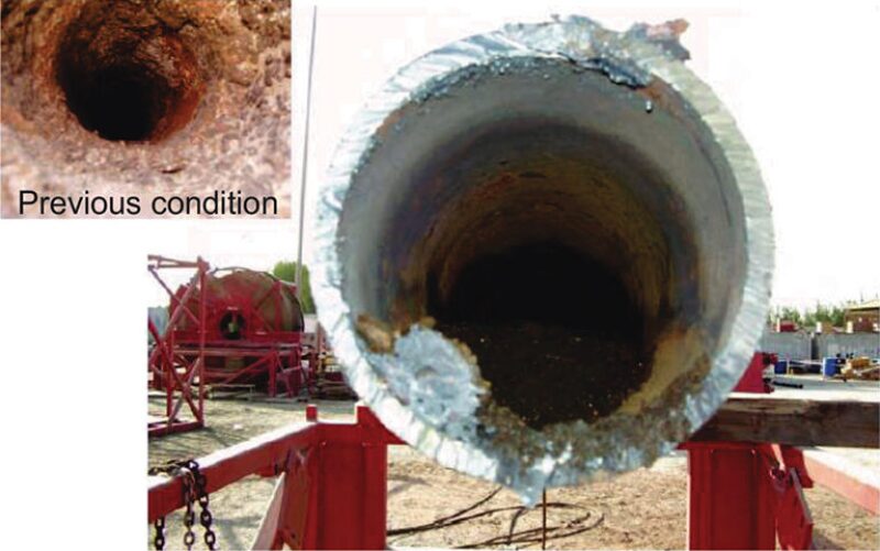
The second run was completed with the slow-rotating power module equipped with a fluidic-oscillation-type nozzle. This nozzle has a higher pressure drop than the jets on the mill used in the preceding run. The oscillating-jet action aided the dislodging of scale from the tubulars with a high impact force generated by pressure pulses. The tool produces alternating bursts of pressure on each side of the nozzle head, which create pulsating pressure waves within the wellbore. As each fluid-stream burst is released, it forms a compression wave within the wellbore. When the wave strikes the tubulars and scale, it bounces back, disseminating energy within the attached scale. This constant impact (up to 300 times per second) induces tensile-loading fatigue on the scale material and eventually breaks it up. These pressure waves will break the scale along the entire circumference of the tubulars because these pressure waves expand spherically, providing 360° coverage, even if the tool is not rotating. The pressure drop across the tool is 2,000 psi at 3 bbl/min, and a pulse frequency of approximately 300 Hz is generated. Fig. 1 above shows a yard test performed with FeS-scaled tubulars to demonstrate the effectiveness of the fluidic-oscillation tool.
Reservoir Isolation
If reservoir isolation were not achieved, the planned descaling and formation-stimulation jobs would be canceled. Therefore, a strategy was developed to control the well by temporarily sealing off the formation to prevent formation-fluid influx and minimize circulation losses when lifting the scale cuttings.
Two types of treatments were planned for the isolation of this naturally fractured carbonate formation with approximately 3,400 ft of 5⅞-in. openhole laterals: LCM pills having particle-size distributions the same as those used during the drilling phase in offset wells and a chemical packer (as contingency). The LCM pill consisted of a combination of calcium carbonate particles, spun mineral fibers, and different sizes of calcium carbonate flakes. (The concentration of each component varied depending on the severity of losses.) The chemical packer was a fully borate-crosslinked polysaccharide polymer, forming a stiff gel. The LCM pill and chemical packer were designed and formulated to be 100% acid soluble and to resist decomposition at bottomhole conditions for at least 3 days.
Reservoir Stimulation
Openhole cleanout and hydrajet acid stimulation were performed in a single 2⅜-in.-CT trip. Although the well was completed with two openhole laterals of different lengths, previous interventions and deviation surveys indicated a tendency of a CT bottomhole assembly (BHA) to enter the last hole drilled, in this case to total depth of 13,400-ft measured depth (MD). Therefore, the stimulation strategies focused on this lateral without the use of steering tools.
Key components of the BHA included a fluidic oscillator and the hydrajet tool with a ball-actuated isolation sleeve. The fluidic oscillator, with 4-bbl/min inserts at the tip of the BHA, was used primarily for obstruction removal and to remove excess plugging material in the openhole section to provide the optimum tool frequency, optimum pressure drop across the nozzles, and the required fluid velocity for particle lifting. The hydrajet tool with ball-actuated isolation sleeve was fitted with four 3/16-in.-diameter jets at 90° phasing. The optimum pressure drop across each jet would be approximately 2,500 psi at 1.2 bbl/min. The purpose of the sleeve was to isolate the injection ports while pumping down to the fluidic oscillator during openhole cleanout. Once the targeted laterals were free of obstructions, a ¾-in.-diameter ball was released to shear the sleeve pins and open jets to CT flow at the same time that the fluidic-oscillator nozzle was isolated.
The greatest targeted depth for the first acid-hydrajet treatment interval was set at 13,350-ft MD in this lateral. However, because of the limited penetration observed beyond 12,460-ft MD and after re-evaluating operational risks associated with this situation, it was decided to distribute the acid-hydrajet intervals throughout the cleaned openhole section—12,460- to 12,150-ft MD, spaced every 50 ft. When the CT hydrajet reached 12,450-ft MD, the ball to slide the sleeve was launched, followed by pumping gel and treated water. Because of the sour nature of this well, the operation time, and the HCl concentration, all precautions to help prevent corrosion were taken into account.
Each acid-hydrajet stage consisted of inhibited gelled 26% HCl injected for approximately 15 minutes, followed by a solids-free nondamaging diverter for fluid-loss control. During acid injection, the average pump rate was approximately 4.2 bbl/min, with an average pump pressure of 6,800 psi, indicating that optimum pressure drop across the jets was achieved.
Matrix acidizing of the reservoir was the ultimate goal of this challenging well intervention. The stimulation strategy (a sequence of organic solvent, acid blends, and solids-free nondamaging diverter) was applied to this formation effectively. The stimulation treatment was designed to remove or bypass any formation damage caused by organic compounds, inorganic compounds, fluid retention, or wettability changes. It was designed to provide an effective acid diversion and accelerate post-stimulation cleanout. The matrix-acidizing job was pumped as designed.
Results
The chemical-plug formulation was effective and will be used for subsequent temporary isolations for scale-cleanout operations. The motor/mill run was performed successfully as per the program; although there were some hard tags where having both mechanical and chemical means proved valuable to continue the operation. The slow-rotating blasting tool cleaned the tubing and liner sections successfully, recovering fine-grained scale at surface.
During the final stimulation run, the CT was run in the hole with the fluidic-oscillation tool to clean out the LCM and the chemical plug in the openhole section. At 12,460-ft MD, a hard tag occurred. Attempts were made to pass this obstruction, but without success. It is suspected that there was formation material in the wellbore that obstructed passage. The CT stimulation proceeded from the maximum reached depth and then was pulled out of the hole to perform a bullheaded matrix-acidizing program.
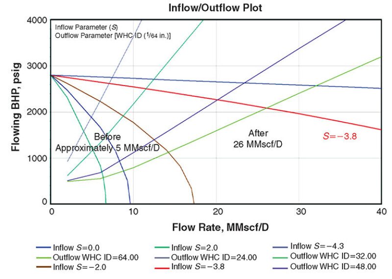
After the stimulation was completed, well production and the wellhead pressure increased, indicating improved connection with the reservoir and increased ultimate recoverable reserves. Before the intervention, the well had a very low shut-in BHP of 1,215 psi. After the acid treatment, the well produced 27 MMscf/D of gas at a wellhead pressure of 2,100 psi—an increase in production of more than five-fold. With this information, a new nodal-analysis simulation was run, yielding a considerable decrease in skin (down to −3.8) evidence of a successful stimulation treatment. Fig. 2 compares the pretreatment and post-treatment conditions of the well, showing its calculated skin.
This article, written by Dennis Denney, contains highlights of paper SPE 169759, “Extreme Challenges in FeS-Scale-Cleanout Operation Overcome Using Temporary Isolation, High-Pressure Coiled Tubing, and Tailored Fluid Systems,” by Mustafa Buali, Noel Ginest, SPE, Jairo Leal, and Oscar Sambo, Saudi Aramco, and Alejandro Chacon and Jose Vielma, Halliburton—Boots & Coots, prepared for the 2014 SPE International Oilfield Scale Conference and Exhibition, Aberdeen, 14–15 May. The paper has not been peer reviewed.