An ongoing research project started nearly 3 years ago by the US Department of Energy’s National Energy Technology Laboratory (NETL) is shedding new light on what really happens to foamed cement as it is pumped deep down offshore wells during completions.
The genesis of the research was the 2010 subsea blowout of the Macondo well in the US Gulf of Mexico (GOM) that destroyed the Deepwater Horizon drilling rig and claimed 11 lives. In the aftermath, the industry faced tough questions about the limits of its technology and the US government tapped NETL to improve the safety of offshore development.
After 6 months of interviewing experts in the offshore industry, lead researcher and NETL scientist Barbara Kutchko, who served as an objective expert in the federal litigation over the Macondo incident, decided to focus on foamed cement based on the clear need for more information about how the technology performs outside of the laboratory.
“I knew there was a big issue with foamed cement,” Kutchko said. “There was not a lot of research behind it. Foamed cements are mixed under atmospheric conditions, yet there was little known about its properties in the wellbore.”
Cement specialists who are lending their expertise to the research said initial findings confirm long-held theories about how the 25-year-old technology performs. As the work progresses, they also said it may result in improvements in how foamed cement is made and applied.
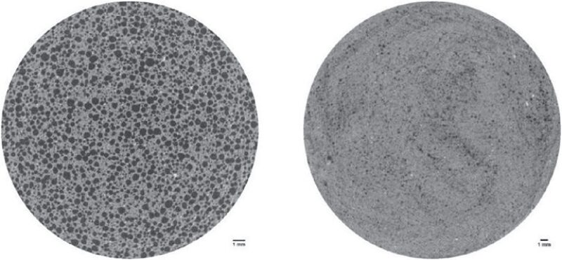
Among the things that the research has proved thus far is that as the density of the bubbles inside the foamed cement varies, so does its strength. When the bubbles are smaller, the chances of them joining together to form a larger bubble is less likely, resulting in higher quality and stronger cement.
Foamed cement was first introduced in the early 1980s as a low-density substitute for conventional cement and can be pumped more easily down deep wells. In the offshore environment, where deck space and weight are always at a premium, lighter-weight foamed cement has also greatly improved the logistics of completing subsea wells.
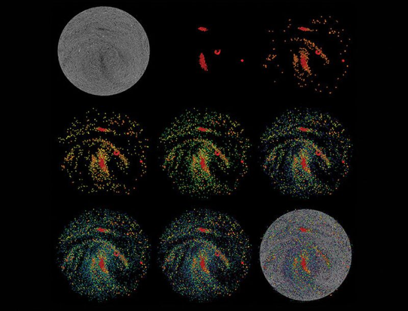
Kutchko said her laboratory specializes in simulating subsurface environments, making it the ideal facility for the study of foamed cement. And what makes the NETL team’s research groundbreaking is that it involves a medical- and industrial-grade computerized tomography (CT) machine to produce 3D images of samples taken from cement treating lines at service company test sites.
“We now have X-ray vision,” said Glen Benge, a consultant with Baker Hughes and a retired ExxonMobil engineer who carried out the first-ever foamed cement job on an offshore rig in the GOM. “We can actually look inside the pieces of pipe and see what is going on, which before, we were not able to do when it is under pressure.”
Benge is one of several experts using NETL’s findings to help rewrite the 25-year-old foamed cement testing standards for the American Petroleum Institute (API). Major oil companies represented in the API’s work group on cement testing include BP and Chevron.
Some experts from the service companies said the new data will help them come up with improved ways to make foamed cement and predict how it will work under various wellbore conditions with greater accuracy.
Gunnar DeBruijn, a manager of cementing at Schlumberger’s North American operations and a member of the API work group, said NETL’s research has been instrumental in helping develop new standards. “I think that the images they are generating are amazing and as an engineer, it is really fascinating,” he said. “Any time you can understand your material a little bit better, then you can maybe improve the design.” He added, that continuous improvements will lead to more confidence and assurance that well integrity and zonal isolation are achieved with the use of foamed cement.
The initial phase of NETL’s research has focused on the influence of flow and pressures between 500 psi and 1,000 psi, which are not influencing factors involved with lab-generated samples. In the future, Kutchko said NETL would like to explore other factors such as temperature and pressures above 1,000 psi to better replicate offshore wellbore conditions.
Spotlight on Foamed Cement
Because of his long working experience with foamed cement, Benge served as an expert witness in the US federal inquiry into the cause of the Macondo well blowout. During his testimony, he concluded that the cementing issues at play were due to poor communication between the engineers responsible for the cement job, combined with a flawed design and its implementation, but not the foamed cement technology itself.
As happens after many engineering disasters, the Macondo incident provided the offshore oil and gas industry with an opportunity to learn new information about an underappreciated yet critical technology. “It highlighted that cementing is important,” Benge said. And as a result, “We have seen a lot more emphasis on it over the last 4 years,” he said.
An example of the increased scrutiny is a new GOM regulation for operating companies that requires every casing and cement operation to be signed off by a licensed engineer. And despite the long track record of foamed cement success offshore, the empirical evidence to prove how and why it does its job has been lacking; hence, the impetus for the NETL study.
While the US government funds the research, service companies and operators support the effort through donating materials, samples, and their experts’ time to help understand the results and advise researchers on their experiments. In turn, NETL updates the API with its progress every 6 months to aid in the rewriting of the recommended best practices for testing.
The hope is that the research will make a measurable difference in how offshore wells are cemented in the near future. One way this goal can be reached is by developing never-before-used predictive models that can tell companies how the gas bubbles inside foamed cement affect its performance.
Kutchko praised the companies involved for their willingness to set aside their usual competitiveness and share intellectual property for the greater good of improving offshore safety and the outcome of the research. “The support that we have received from the industry has been, I almost have to say, unprecedented,” she said. “It has been a really important partnership. We can do things together that we cannot do by ourselves.”
Beyond the Lab
When creating foamed cement samples in the lab, it is a simple task to take measurements of porosity, permeability, and strength, but this is not the case once it is pumped downhole in a real-world application.
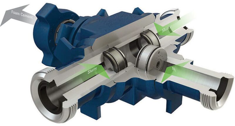
Foamed cement is made by injecting a high-pressure stream of gas, usually nitrogen, into a cement slurry mix, like the milk frother on a cappuccino machine. Other additives including foaming agents, surfactants, and chemical stabilizers are used too.
The foamed up mix is then injected down the production casing at various drilling intervals. When it hits bottom, the slurry is pushed up the annulus to create a barrier between the casing and rock and to support the casing section.
What exactly happens to the slurry as it moves deeper into the well and annulus remains difficult to assess. Without a surefire way to know, companies rely on conservative estimates of how strong the cement needs to be to ensure well integrity, i.e. they must overcompensate.
To fill the gap with reliable data, NETL researchers have focused much of their efforts on obtaining and studying samples of field-generated foamed cement from a specially designed sampling manifold.
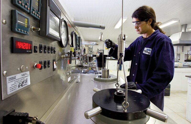
NETL worked with Baker Hughes, Halliburton, and Schlumberger, which together represent the lion’s share of the offshore cementing market, to obtain three sets of foamed cement samples from each of the companies’ field testing facilities. The samples were allowed to fully cure, so that the structure of the foamed cement would not be disturbed, before being delivered to NETL’s facility in Morgantown, West Virginia, in 2-in diameter by 3-ft long pressure vessels known as constant pressure sample cylinders. Refiners use the same type of sample cylinder to collect fluids flowing through high-pressure pipes.
NETL researchers then compared those samples with the lab-generated samples made with standard lab equipment as well as a high-pressure foamed cement generator on loan from Schlumberger. Before the CT technology was used for this application, companies have tried to analyze foamed cement by injecting it into iron capsules, letting it set, and then cutting the capsules in half. However, this method does not account for many factors, such as flow, at play inside an actual wellbore.
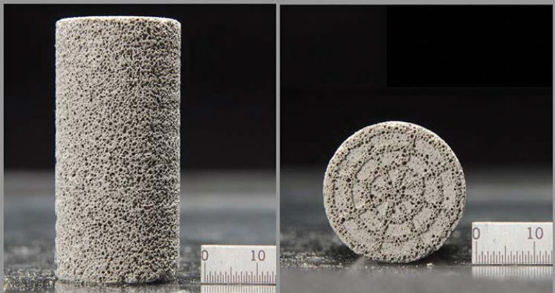
In lab-generated samples, the nitrogen-filled bubbles tend to be uniform in size and evenly spaced. “I could mix 1,000 samples in the lab and they are all going to look like that,” said Kutchko. “But when you take it out in the field, there are so many different parameters that are impacting the distribution and size of these bubbles.”
To replicate field-like conditions for NETL, the service companies pumped wet slurry through treatment lines at pressures of 500 psi and 1,000 psi and then carefully extracted them. To accomplish this, the engineers developed a new method to capture the cement slurry at pressure and under flow.
“It was a big undertaking as far as being able to capture these under pressure and in-field conditions,” said Charles Buford, a foamed cement expert and applied engineer at Baker Hughes who helped design and oversee the extraction of the samples and is a member of the API work group on foamed cement. He said the CT scans he has seen validate some of the industry’s predictions about bubble size and distribution.
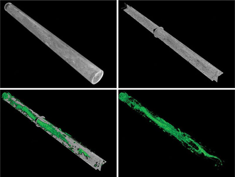
NETL’s research found that the biggest influencer in bubble distribution was the flow motion of the cement slurry. The CT scans show a moment frozen in time as the flow ended and the cement began to set, revealing both low- and high-porosity areas all along the 3-ft-long sample.
NETL believes that some of the larger bubbles were formed by smaller bubbles joining together, a physical change that cannot be undone as the cement begins to harden. The way these bubbles formed inside the sample cylinders flowed should help broaden the understanding of how foamed cement slurry behaves as it flows into the annulus of an actual wellbore.
By comparing the lab-generated samples with the field-generated ones, the bubbles from the field samples were smaller, and, thus had lower porosity. This supports what cement specialists have believed about the behavior of foamed cements in downhole conditions.
“We had our theories that the bubble size distribution in these slurries was much finer and better distributed than what we were seeing in our lab-generated samples and some of these preliminary looks we have had actually show that,” Buford said. “Now we know where we are at in the labs, and what it looks like in the field.”
Room for Improvement
While some of the data has provided assurance to the experts, Kutchko said questions that need answers remain, warranting continued research. The field-generated samples show that the bubble size and distribution varies from foot to foot and is highly complex.
While the sample cylinders used and pressures were the same, as part of the experiment, each sample was generated under slightly different conditions. “And the outcome changed each time,” Kutchko said. This is something she wants to know so companies can understand how the changes affect the strength of the cement.
And when some of the samples were depressurized and cored out for testing, Kutchko said they broke or cracked along the areas that had a higher proportion of gas bubbles. However, she said that this observation might not be the best way to predict strength.
“Under the wellbore pressures and hydrostatic pressures in the wellbore, maybe that will not be a problem,” she said, adding that this is another example in which more data is required as no one has yet to devise a way to test for strength in-situ.
Once in the well and given enough time to set, pressure tests are the primary method of verifying that foamed cement is holding true. Cement bond logs can also be used, but when applied to wells that have foamed cement in them they are not a reliable testing method because of the material’s low density. “There really is not a good way that I know of to ensure that the foamed cement is where it is supposed to be in the well and is doing what it supposed to be doing,” Kutchko said.
Despite the unknowns, Kutchko said the research completed thus far is highly valuable and she expects to release the data for companies to use in their foamed cement designs later this year.
DeBruijn said Schlumberger has already developed plans to use the results and data once they are made available. “There are some exciting things coming in our software and simulators” for foamed cement, he said. “We will be able to update our modeling more appropriately so we understand how we are placing things in the wellbore.”
With updated models, wellbore data, and wellsite execution data, DeBruijn explained that the company wants to simulate the placement of the cement in the annulus and integrate that information with logging data to enhance the confidence that cement barriers are where they should be.
When the NETL research is completed, the industry may have all the answers it needs to know about how the generation of foamed cement can be further improved, how large should the bubbles be, and how many of them are needed to provide the strength and permeability that companies are expecting to benefit from their formulas.
Benge credits Kutchko and her research at NETL for providing optimism that those goals are within reach. “I think her work is going to go a long way in helping us understand those things and give us better assurance that when we are applying this technology, the field materials we are putting in a well are actually going to work,” he said.
For Further Reading
SPE 9598 Foamed Cement—A Cement with Many Applications by David Davies and Jan Hartog, Shell Exploration and Production Lab, et al.
SPE 170298-MS Assessment of Foamed Cement Used in Deep Offshore Wellsby Barbara Kutchko, NETL, et al.
OTC 8305 Successful Cementing in Areas Prone to Shallow Saltwater Flows in Deepwater Gulf of Mexico by Dave Stiles, Schlumberger.
SPE 20116 The Determination of the Static and Dynamic Properties of Nitrified Cements by Dan Mueller, The Western Company of North America, et al.

