

Long subsea tiebacks to existing host facilities are of great interest to many offshore operators since they allow for fast-tracked projects, help maximize the value in using existing infrastructure, and they maintain throughput for the host facility as older well production declines. With flowline length having increased over the years, the economic impact of dual flowlines has become prohibitive, thus raising operator interest in single-line tiebacks. However, while they can be beneficial, an expert said that long tiebacks have their own potential pitfalls, with flowline blockages being a major hazard.
In a presentation held by the Society of Underwater Technology—Houston, Melissa Gould examined the advantages and disadvantages of long subsea tiebacks, including operator concerns of hydrate or paraffin blockages that may occur when using them. Gould is a principal at Stress Engineering Services, leading the subsea pipeline, equipment, and controls group in the company’s upstream practice.
Fig. 1 details the number of blocked flowlines in the US Gulf of Mexico reported to the US Bureau of Safety and Environmental Enforcement (BSEE) from 1978 to 2014. Of the 124 blocked flowlines reported, 99 have been identified as paraffin blockages, and 25 were identified as hydrate blockages.
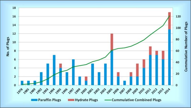
BSEE did not include blockages caused by asphaltenes in its reporting, nor did it include temporary hydrate blockages that did not force the shutdown of a flowline, but regardless Gould said the data indicated an upward trend, and the industry must examine why these blockages are still occurring. If operators cannot solve the blockage issue for shorter dual-flowline tiebacks, they could not be confident of success with long tiebacks. In asking this question to different operators, Gould said she received a plethora of answers.
“When I asked various operators that question, this is when all bets were off. I had one operator tell me that they had done an internal analysis of every one of their blockages and they all came back to human error. I had another operator that was adamant that it was whether or not the field was properly designed for the full field life at the start. This operator was adamant that you spent the money and you did your design work upfront for the full life, and actually spent your Capex ahead of time, that would reduce your Capex quite a bit. We had the full range of answers depending on who we spoke with,” she said.
Some common methods established during the design phase of a project to prevent hydrate formation include passive flowline insulation such as wet insulation or pipe-in-pipe. Operators could also rely on continuous or intermittent injection of either a chemical inhibitor, methanol, glycol, or a low-dosage hydrate inhibitor (LDHI), though Gould said injection comes with its own pitfalls like high costs and logistical difficulties.
Gould said that if a chemical injection is defined either on a continuous or intermittent basis, the prescribed dosage rate of the chemical must be rigorously maintained, with the downtime not exceeding the defined limit. Periodic sampling and requalifying of the chemical inhibitors in changing field conditions is also important, along with frequent monitoring of the flowline for buildup on the pipe wall.
There are several commonly available mitigation and remediation methods for operators to use when chemical injection fails, including pressure blowdown, hot-oil treatment, pressure pulsation, warm-solvent washing, and coiled tubing intervention for flushing and cutting a hydrate blockage. Companies are also examining newer techniques such as localized flowline heating through electrically traced heated blankets and other methods, as well as injecting high density/low-surface-tension chemicals into the flowline.
Active flowline heating systems can also be effective at preventing hydrate formation. Gould discussed three such systems: direct electrical heating (DEH) with wet insulation or pipe-in-pipe, electric trace heating (ETH) with pipe-in-pipe, and electric heating in an integrated production bundle.
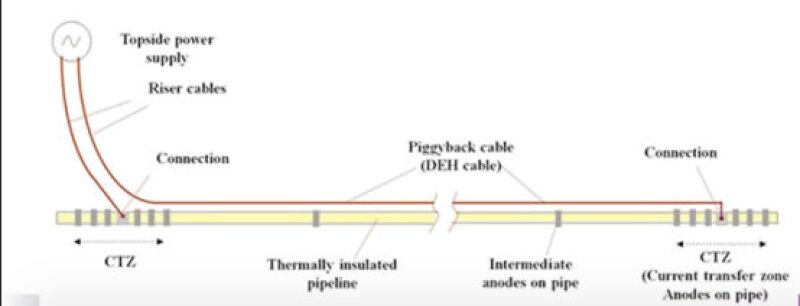
A DEH system (Fig. 2) includes a riser cable supplying power from the platform to the seabed. A feeder cable connects the riser cable to the flowline and a piggyback cable, which conducts the current to the far end of the flowline. The heating system is electrically connected to the seabed through sacrificial anodes which must be rated for corrosion protection and sufficient grounding of the system.
ETH with pipe-in-pipe has only been executed in one field: Total’s Islay Field, located 440 km northeast of Aberdeen in the UK North Sea. Developed by Technip for use in the field, the system brings active heating through three-phase electrical tracing cables that end with a star connection where the sum of the three current phases is zero. This avoids the need for a current returning path. Tracing cables run below the thermal insulation and are in contact with the flowline. Gould said this improves power transmission from the electrical cables to the fluid, thus minimizing heat loss, and overall power consumption is lower compared to a DEH system.
Video: A closer look at the flowline system for Total's Islay field. To mitigate hydrate issues, Total utilized an electrically trace heated pipe-in-pipe system.