
Factors such as hydraulic gradients in the horizontal completion, geologic and fluid variations in the reservoir, and well-placement issues can produce very poor steam conformance in steam-assisted gravity drainage (SAGD). Using proportional-integral-derivative (PID) feedback to control steam injection can lead to improvements in SAGD. Inflow- or injection-control devices (ICDs) can also improve SAGD performance. This paper examines detailed wellbore simulations of a SAGD process in which wells are equipped with a combination of ICD completions and feedback control to determine the physical mechanisms and outline practical procedures to determine an improved ICD completion and feedback-control design.
Introduction
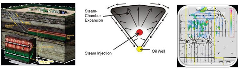
SAGD is the most extensively used process for development of the bitumen resources in western Canada. Fig. 1 shows the concept of this process in which two closely spaced horizontal wells are placed such that the upper well injects steam and the lower producer collects reservoir fluids that drain mostly by gravity from a constantly evolving steam chamber. Ideally, the steam chamber evolves uniformly along the entire length of the well pair. However, the actual pattern of SAGD well pairs shows very irregular steam-chamber development along the lengths of most of the pairs in the pattern.
For many years, SAGD operators in this region have been evaluating methods to improve conformance along well pairs. One such method is to install dual-tubing strings in the injector and producer. Prescribed injection and production rates from each tubing string may be determined from a reservoir-engineering analysis of the formation around the pair, but such analyses are often inexact. In order to prevent the steam chamber from touching the lower producer, which would then remove hot steam instead of using it more efficiently in the upper reaches of the chamber, the injection and production rates are usually set to maintain a prescribed temperature difference between fluids exiting the upper injector and entering the lower producer. This temperature difference, also referred to as a “subcool” because it is set to be several degrees below a water saturation temperature, may be controlled at both the heel and the toe of the well pair by use of the ability to inject and produce from the two tubing strings that are landed at these points. However, setting these injection and production rates to reflect the current state of the reservoir and current subcool is difficult with conventional reservoir-engineering analysis. To improve on this, a proposal was made to use a feedback controller to monitor temperatures of produced and injected fluids automatically, with a target subcool at the heel and the toe of the well pair. By targeting the same subcool at the heel and the toe, two objectives are accomplished: (1) achieving the subcool prevents steam from entering the lower producer, and (2) both toe and heel halves are encouraged to produce uniformly because both are targeting the same subcool (i.e., if one-half temporarily operates at a lower or higher subcool than the target, steam injection is decreased or increased, respectively, in that half to compensate).
Another method to improve conformance is to install carefully constructed ICDs in either the injector or the producer, or in both. When placed in the injector, these devices can equalize the outflow of steam from heel to toe better, regardless of variations in reservoir mobility properties.
PID Controller
For the dual-tubing cases examined here, the short tubing string in both wells is landed at the heel and the long tubing string is landed at the toe. Two separate controllers are used for the heel and toe tubulars, each with its own error term. See the complete paper for the controller and error term equations.
When a controller with an error term is used to control the injection rates of dual-injection-tubing strings, each of which is targeting a specified subcool to the nearest region in the lower producer, the objectives of meeting a subcool target and of improving conformance are both met. Steam chamber uniformity is improved because each controller operating on different regions of the well pair is attempting to achieve the same specified subcool.
ICD Design To Control Conformance, Subcool, and Unwanted Water/Gas
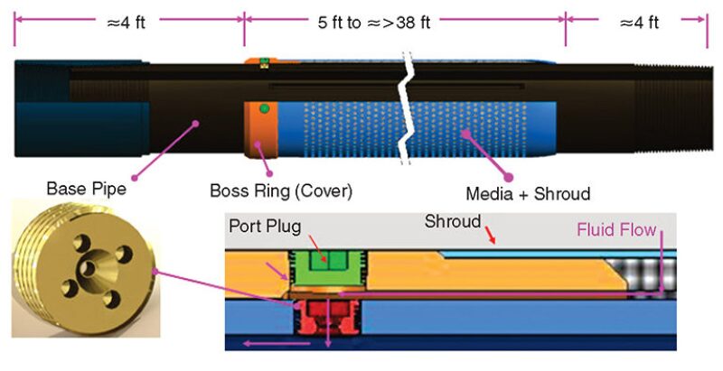
For this study, a high-temperature ICD design was chosen that combines a sand-control screen with a choke that is designed to give a linear production or injection profile throughout the length of the horizontal wellbore. These devices are installed in 7-in. base-pipe joints, each with a length of 46 ft. Each joint is equipped with flow-constriction nozzles. Flow across the nozzles produces a Bernoulli relation (pressure drop vs. flow rate). Fig. 2 is a schematic of the device, including dimensions, outer screens, flow paths, and a picture of the nozzle.
Case Studies
Four cases were run. These included combinations of dual-string injection with PID control and wells equipped with ICDs. The first case, PID injector/ICD producer, was configured with an injector containing dual 3-in.-inner-diameter (ID) tubing strings landed at the heel and toe and in which steam-injection rates to the heel/toe strings were PID controlled with a specified subcool target. The producer was equipped with ICDs and, hence, contained only a single 6.3-in.-ID tubular with no additional tubing string landed at the toe. For the second case, PID injector/dual-string producer, the injector and producer both contained dual-tubing strings. The injector was PID controlled by a heel/toe subcool target, and the producer produced equally from both heel and toe tubing strings. The third case, ICD injector/ICD producer, contained both injector and producer fitted with ICDs along their entire horizontal length. Again, there was no additional tubing string landed at the toe for this case. The fourth case, dual-string injector/dual-string producer, was a base case in which the injector and producer both contained dual-tubing strings, steam injection rates were constant and equally split between the heel and toe strings, and production was split also between heel and toe.
Results
One of the benefits of installing ICDs in an SAGD injector is to allow a higher heel injection pressure, which means that there is higher enthalpy delivery to the reservoir for a given mass rate and that steam quality increases across the nozzle because of the pressure drop.
At 2 years, temperature and gas-saturation profiles are similar between the three cases—PID injector/ICD producer, PID injector/dual-string producer, and ICD injector/ICD producer. ICD injector/ICD producer displays a slightly greater coolness in the midregion and lower gas saturations although with similar chamber growth near both ends, possibly because injection and production are both occurring only at the heel, while the first two cases have injection at both the heel and the toe. All are showing a good degree of uniformity along the length of the well pair.
By 7 years, the two PID-injector cases are showing equivalent steam-chamber growth along the entire length while the ICD-injector/ICD-producer case is showing slightly less growth near the toe. Temperatures in the first case (PID injector/ICD producer) are looking somewhat cooler than those for both the PID-injector/dual-string-producer and ICD-injector/ICD-producer cases because the PID controller in the former is just beginning to hit its subcool target at this time (7 years) and the second PID case will achieve this shortly after.
By 12 years, the first two PID cases are showing cooler steam chambers than the ICD-injector/ICD-producer case because both are achieving their subcool targets.
The two cases with dual-string producers, dual-string injector/dual-string producer and PID injector/dual-string producer, show very large, uncontrolled subcools up to approximately 5.5 years, while the two ICD cases show controlled subcool throughout the production cycle. The PID-injector/dual-string-producer case does eventually start to control the subcool. The base case, with dual strings in both injector and producer and no subcool control, shows very low subcools at times greater than 5 years, but this is because the steam chamber is touching the producer at these times. The case with ICDs in both injector and producer exhibits very low subcool at times greater than 5 years; but, again, the steam chamber is getting close to the producer. The PID-injector/ICD-producer case shows good subcool control in the early stages and the ability to achieve a subcool target in the later stages.
At 2 years, the two cases with PID injection, PID injector/ICD producer and PID injector/dual-string producer, show similar pressure profiles around the well pair except that the case with the ICD producer shows flatter profiles than the case with the dual-string producer. This is expected because of the benefits of the ICDs in evening out inflow to the producer.
At 7 years, the PID-injector/ICD-producer case is showing lower pressures because the PID-injector has already begun to achieve its subcool target, which the second PID injector case has not yet accomplished. Pressure profiles for the other two cases, PID injector/-dual-string producer and ICD injector/ICD producer, are very similar.
By 12 years, the two PID-controlled injection cases are showing comparable low pressures around the well pair, while the ICD injector/ICD producer case is showing considerably higher pressures because steam has broken through to the producer and is causing higher pressure drops across the ICD nozzles.
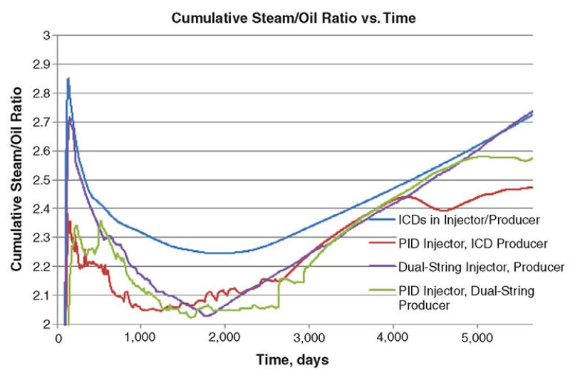
Fig. 3 presents a comparison of cumulative steam/oil ratio for the three well-pair configurations and the base case.
Discussion
The results suggest that a hybrid method of using feedback- (PID-) controlled steam injection from dual-tubing strings with a producer equipped with ICDs may have several benefits. First, there are reduced capital and operating expenditures because there is one less tubing string in the producer. Second, an ICD-equipped producer provides a more-even inflow, which results in better-controlled subcool throughout the production cycle, particularly in the early stages after switch-over when it is more difficult (or impossible) for PID-controlled steam injection to achieve a subcool target. Third, later in the production cycle, the ability of the PID-controlled injection to force a specified subcool target appears to keep the steam chamber farther from the producer and improve the economics of the process.
This article, written by Special Publications Editor Adam Wilson, contains highlights of paper SPE 163594, “Advanced Wellbore Simulation of Flow-Control Devices With Feedback Control for Thermal Operations,” by Terry Stone, SPE, Schlumberger Information Solutions; Carlos Emilio Perez Damas, Schlumberger Calgary Regional Technology Centre; Glenn Woiceshyn, SPE, Absolute Completion Technologies; David Hin-Sum Law, SPE, Schlumberger Calgary Regional Technology Centre; George Brown, Schlumberger Fibre Optics Technology; and Peter Olapade and William J. Bailey, SPE, Schlumberger-Doll Research, prepared for the 2013 SPE Reservoir Simulation Symposium, The Woodlands, Texas, USA, 18–20 February. The paper has not been peer reviewed.