The majority of mechanical equipment found in oil and gas facilities belongs to the static equipment group, which comprises pressure vessels (drums, columns, reactors, filters) and heat exchangers (shell and tubes, plate and frame, air coolers).
The presented guidelines contain cost-effective recommendations for their design, materials, and fabrication. They aim to enable the project engineer, who is not an equipment specialist, to check that economical choices are made.
The specification and selection of the equipment is the responsibility of the static equipment engineer, based on requirements specified by other disciplines, including process, materials and plant layout.
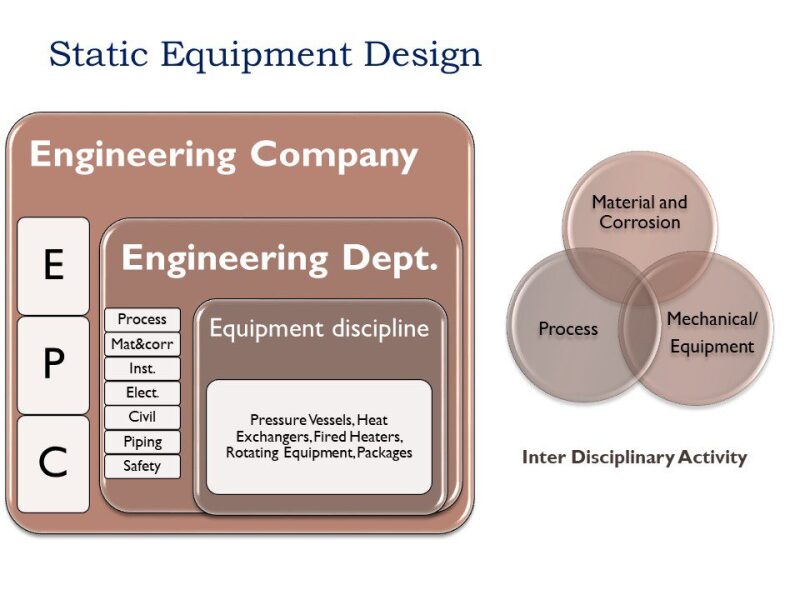
These other disciplines are not always aware of the impact of their demands on the cost/lead time of the equipment. Conversely, the static equipment discipline is not always aware of where the requirements of these disciplines come from and if the onerous ones could be challenged. Such interface data are the focus of this article, which aims to give a cross-discipline awareness.
Let’s start with the review of the process equipment data sheet.
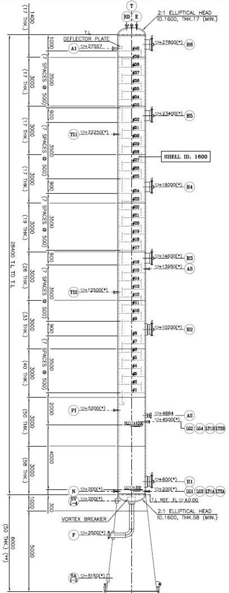
Process Equipment Data Sheet
In this example, the process equipment data sheet contains the following information:
- Inside diameter, tangent line to tangent line (TL) length, overall length,
- Service (type of fluid)
- Special service (hydrogen, sour, cyclic, lethal)
- Presence of chlorides
- Vessel orientation (vertical/horizontal)
- Maximum allowable working pressure design pressure (MAWP) and temperature (MAWT)
- Design for full or partial vacuum
- Minimum design metal temperature (MDMT)
- Type of heads
- Internals type and position (i.e., demister)
- Nozzles (process/instrumentation) list with sizes, service, and position
- Skeleton vessel sketch
- Generic material of construction (wet parts) and corrosion allowance
- Type of nozzles (butt weld/flanged)
- Rating and type of flange (raised face/ring-type joint)
- Insulation (yes/no)
- Heat tracing/winterization, or steam coil
- Passive fire protection
- Site conditions (wind, seismic, blast; or reference to the project document containing such information, e.g., basic engineering design data
- Hazardous area classification
Design Pressure
The process engineer defines the design pressure by applying common and reasonable margins above the maximum operating pressure, as shown below.
Max. operating pressure | Design pressure |
|---|---|
Atmospheric pressure | 0.5 barg |
Vacuum | Full vacuum and 3.5 barg min. |
Between 0 and 10 barg | Max. op. press. + 1 bar (3.5 barg min.) |
Between 10 barg and 35 barg | Max. op. press. + 10 % min. |
Between 35 barg and 70 barg | Max. op. press. + 3.5 bar min. |
Above 70 barg | Max. op. press. + 5 % min. |
Design temperature
The design temperature is usually set 15-20°C above the maximum continuous operating temperature. It shall not take into account accidental temperatures which can happen for short duration only, during startup, shutdown, or in emergency conditions, e.g., loss of utilities, valve failure.
The design temperature must take into account the potential bypass of the upstream heat exchanger for cleaning, as well as the scenario of stopped upstream air-cooler fan(s).
The design temperature must take into account alternate operating conditions of significant duration, such as regeneration, dry-out, and steam-out. However, the temperature reached in these conditions might not be concurrent with the maximum pressure for which the vessel is designed. In such case, the combination of temperature and pressure in these conditions must be considered together.
To download this article as a pdf, click here.
Flange rating
It is worth noting that the selected design pressure and temperature does not result in an unnecessary flange rating upgrade, e.g., from 600 lb to 900 lb, by reviewing the ASME B16.5 tables for flanges up to nominal pipe size 24 in., and B16.47 for larger pipes. If the design P, T are very close to a boundary between flange ratings for the selected material, it is worth challenging the P, T design criteria.
Minimum design metal temperature (MDMT)
The MDMT is the lowest between minimum fluid temperature and the temperature caused by autorefrigeration upon fast depressurization, which is carried out, for instance, in case of emergency (gas leak).
Be careful in selecting the correct MDMT because a lower-than-required MDMT could result in a change of material or, for carbon steel, special heat treatment or impact test, which adds to the cost.
In cold climates, the MDMT does not need to be the minimum ambient site temperature. Indeed, the equipment could be started up slowly so that it warms up while its internal pressure is raised. It simply requires a proper startup procedure that ensures warm up before the full internal pressure is applied.
The thresholds that may require a change of material, special heat treatment, or impact tests are -29°C and -48°C. Specifying a design temperature below -48°C implies a special qualification of all welders and weld procedures, which many fabricators may not have developed.
Design for vacuum
Vessels are designed for vacuum if they may operate at lower than atmospheric pressure. Another usual case is when steam could be used to clean the vessel. In case the vessel is isolated after being “steamed out,” which could happen due to operator error (closing of the vent valve), vacuum could develop inside the vessel when the steam cools down. The vessel shall therefore be designed for vacuum for such an accidental case.
Steam-out is not required for all vessels, typically only for the ones handling dirty/viscous fluids such as heavy hydrocarbons. Design for vacuum will not affect the design of vessels with high internal design pressure. On the other hand, it could add stiffening rings or even increase the wall thickness of low-pressure vessels. Hence, for those vessels, check that “design for vacuum” due to steam-out is specified only when actually required, typically with dirty/viscous liquids such as heavy hydrocarbon. When steam-out is required, question the level of vacuum design specified. As standard, “Full Vacuum (FV)” is indicated on the process data sheet. This means that the vessel shall be designed for an internal pressure of 0 bara. Design for “partial vacuum”, e.g., 0.5 bara, might be enough and result in smaller impact on vessel design.
Types of heads
The process engineer usually specifies 2:1 elliptical heads. These are cost-effective for low-wall-thickness vessels.
When selecting the types of heads, the process engineer is only concerned with their volume.
Hemispherical heads are a more economical choice at high pressure (600 lb and above), e.g., for steam drums, as their wall thickness is half that of elliptical heads. There should be no problem in changing to hemispherical heads as the volume is increased.
Sour service
In sour (i.e., wet H2S) service, H2S may react with water leading to H2 migrating into the carbon steel. When H2 accumulates in the carbon steel, it can lead to internal cracks. Stress, if present in carbon steel, exacerbates this phenomenon. Hence:
- The equipment exposed to H2S and free (liquid) water must be clearly identified. This shall be done by the process engineer, who shall indicate “sour service” on the process data sheet.
- The requirements to be followed in sour service must be clearly specified
- Identification of “sour service” conditions is done using criteria of international standards, such as NACE MR 0175 for upstream facilities and NACE MR 0103 for downstream facilities, unless a client specification applies. NACE MR 0175 criteria are not straightforward and depend on the combination of the partial pressure of H2S and pH. A proper assessment should be done by the process engineer and documented in order to ensure the identification is properly made and “Sour Service” is neither omitted nor unnecessarily specified.
- Requirements to be followed in sour service are that of the NACE standards referred to above and in many locations are considered a legal requirement. Client specification may impose additional requirements. The NACE MR0175 and NACE MR0103 requirements apply to raw material and manufacturing. The requirements for raw materials allows the use of the usual steel (A516 for steel plates, API 5L, A106, A333 for pipes), provided a few requirements are met, such as limits in chemical composition, maximum hardness, processing, and heat treatment. To comply with these requirements, the raw material must in practice be sourced from higher-quality mills, which may increase cost by up to 5–10%. Fabrication requirements include the maximum hardness of welds, which in practice requires the performance of post-weld heat treatment (PWHT), and stress relief in case of excessive cold deformation (e.g., of vessel heads).
- One type of cracking which could take place in sour service, whatever the amount of H2S, is called hydrogen-induced cracking (HIC). This type of cracking is observed on steel plates only. NACE MR 0103 does not address this type of cracking. NACE MR 0175 imposes a very low sulfur content to prevent such cracking and leaves it to the equipment user to assess the risk of HIC testing and specify requirements to resist HIC, in particular HIC test of plates. For the purchasing EPC contractor, this means that the requirements for HIC, if any, are found in client or licensor specifications. HIC-tested plates cost around 50% more. Additionally, as HIC resistance is affected by the steel manufacturing route, testing alone might not be considered sufficient to qualify the steel. Hence some client specifications do not accept steel plates that simply pass the test, which they call “pseudo-HIC,” but impose that they are produced according to a specific manufacturing process, producing extra clean steel (for example, by means of deep degassing). This might restrict the supply of steel plates from only a few sources, impacting the cost and schedule.
Although the task of identifying “Sour Service” conditions falls to the process engineer, who indicated the same on the process data sheet, that of specifying HIC resistance requirements usually does not. It is therefore the role of the equipment engineer to identify if such requirements are present in client/licensor specifications and, in the positive, to specify them.
Lethal service
According to the ASME VIII Code, a lethal substance is a “poisonous gas or liquid of such a nature that a very small amount of the gas or the vapor of the liquid mixed or unmixed with air is dangerous to life when inhaled”. As per ASME VIII, it is up to the user to define if the vessel is in lethal service. The EPC contractor shall identify in the client specifications which are the criteria for lethal service. This shall be the task of the equipment engineer who shall perform a careful review as “Lethal Service” has a big impact on equipment cost and manufacturing: only butt welds are allowed, they shall be 100% X-rayed, PWHT must be done for carbon steel and low alloy, etc. In addition, some client specifications demand integral nozzles for vessels in lethal service. Classification as lethal service should be avoided wherever possible as it has a significant impact on equipment cost for little or no gain: pressure vessels are a negligible source of leak compared to piping flanges. In addition, the Plant is provided with systems to protect the operator against leaks. For toxic gases, these systems include a fixed detection and alarm system, portable gas detectors, and escape masks. Doing 100% X-ray of welds is costly and does not necessarily detect defects as X-rays are subject to interpretation while, in any case, the vessel is subject to a hydrostatic test.
Cyclic service
If a vessel is exposed to a very high number, typically ~100,000, pressure/temperature cycles over its life, it could fail due to fatigue, usually at a weld, unless preemptive measures are taken. These measures include specific welds, such as full penetration, and additional nondestructive evaluation (NDE). The number of cycles that classifies the vessel in cyclic service is given by the pressure vessel code. It is beyond the responsibility of the process engineer to review this. The process engineer shall simply indicate the frequency of change of process conditions so that the mechanical engineer along with the vessel manufacturer check if the vessel falls within the cyclic service criteria of the ASME VIII div 2 code in which case fatigue assessment shall be done as per ASME VIII div. 2.
High temperature service
Vessels working at high temperature may experience creep, a permanent plastic deformation or rupture, that happens even though the stress level in the material does not exceed the level allowed by ASME. The temperatures above which creep must be considered come from Welding Research Council (WRC) Bulletin 470 and are given in ASME. They are the ones for which the stress values are shown in italics in the maximum allowable stress values tables of ASME II part D. For SA-182 F22, for instance, creep shall be considered above 450°C as shown in table 5A.
A time-dependent analysis shall be performed, and requested from the vessel vendor, when creep is to be considered. It shall be performed as per WRC Bulletin 470, “Recommendations for Design of Vessels for Elevated Temperature Service.”
A typical case of vessels which could be subject to creep are reactors subject to occasional regeneration at high pressure. The regeneration condition, frequency, and duration, shall be communicated to the vessel vendor to enable it to perform the time-dependent analysis.
Corrosion allowance (for carbon steel)
Make sure this is optimized, i.e., the result of a calculation such as that using the de Waard and Milliams equation for the usual acid water corrosion of carbon steel. No corrosion allowance shall normally be specified for corrosion-resistant alloys (CRA) such as stainless steel and cladded/overlay vessels.
Design code
The selection of the design and fabrication code determines the vessel wall thickness, extent of NDE, and cost. It is better to leave the choice to the supplier unless a given code is mandatory for regulatory reasons. For offshore application, reduced weight would be another driving factor for selecting appropriate design and fabrication code.
Vessels are only classified as pressure vessels above a certain internal or external pressure, e.g., 15 psig under ASME. Below this pressure they shall be designed and manufactured as per manufacturer standard.
A useful visual presentation of ASME VIII is available here.
European codes have been known to be more economical than the ASME code for high-pressure vessels, as the allowable stresses are closer to the yield point (i.e., the safety margin is lower). For example, by changing from ASME to European code $25,000 was gained on a high-pressure column. If the applicable code is ASME VIII, it is better to leave the vendor the choice between Division 1 or Division 2. Division 2 allows for reduction in the wall thickness by typically 20% by doing more extensive calculations. It is worthwhile considering for high-thickness vessels.
Material selection
It is up to the purchaser, not the vendor, to select the right material of construction based on the fluids characteristics and life span of the equipment.
The process engineer indicates the basic material of construction (e.g, carbon steel). The selection of the steel grade shall be left to the vendor. For instance, the choice between carbon steel A516 grade 60 or 70 is best done by considering the gain in wall thickness by using grade 70 and the difference in cost between the materials.
For nonhydrogen or corrosive service, the material is selected according to the design temperature. The usual selection for plate materials is shown in the table below (references (1), (2) and (4)):

It is good to have some idea of the relative cost of raw materials.

*Dual-certified materials are often available in the market with almost no cost difference. They combine the properties of both “L” and “non-L” grades: 15–20% higher strength of non-L grades + prevention of unwanted sensitization during welding of L-grade.
So specify dual-certified 304/304L to reduce the wall thickness by 15–20%.
Note that there is a tendency by process engineers to specify 316 as stainless steel. It costs 1 EUR/kg more than 304. The only difference is its resistance to chlorides. Check if chlorides are present and, if not, challenge the selection of 316.
In the presence of chlorides, the material selection must take into account the risk of chloride stress corrosion cracking. 316 only qualifies for certain chloride concentrations and temperatures. Duplex, super duplex, or high-nickel alloy might be required. Refer to ISO 21457.
In case of both sour service and the presence of chlorides, consult NACE MR 0175, which includes limitations of temperature for use of austenitic, duplex, and super duplex stainless steels.
Specifying some duplex alloys can actually save cost as they have from 20% to 35% higher allowable code stresses, resulting in a thinner-wall vessel.
For corrosive service, consult the material/corrosion specialist and ascertain the life cycle cost. Replacing the heat exchanger tube bundles is a classic example of a cheaper solution, over the life cycle cost, than using exotic materials.
If the temperature does not exceed 150°C, consider coating the inside of the vessel. Coating a carbon steel vessel can be much more economical than selecting a high-alloy vessel or clad-carbon-steel vessel.
Carbon and low-alloy steels in environments containing hydrogen could be subject to high temperature hydrogen attack at elevated temperatures. Use Nelson curves included in API RP 941 to identify the suitable material based on the operating temperature and H2S partial pressure. 1.25Cr-0.5Mo or 2.25Cr-1Mo are commonly used in hydrogen service.
If you have special alloy vessels, as raw material cost presents a large part of the cost, check how many material quotations the pressure vessel manufacturer got to prepare its bid.
NDE extent
The amount of NDE (% of radiography of welds: full, spot, none) determines the vessel wall thickness: more radiography means less metal. Do not specify the extent of NDE. Leave it to the vendor to choose the most economical (wall thickness, NDE extent) combination in compliance with spec/lethal service requirements if applicable. Gamma rays, which save cost and significant time could be substituted for X-ray if the thickness does not exceed certain limits. Such substitution requires owner approval as per code. It should be assessed based on the criticality of the equipment.
Certification and stamp
Third-party certification and stamp might be required for pressure vessels such as ASME’s “U” stamp for pressure vessels designed and manufactured as per its code. This requires an ASME authorized third party to review documents and perform inspections. It also requires ASME-certified materials. It impacts the documentation, fabrication, and inspection procedures. Such a stamp is not a requirement of the ASME code: all vessels designed and manufactured to ASME need not necessarily be stamped. The stamp is a requirement from the local regulations/law or the client. It brings significant additional cost. It is a time-consuming process, involving stages of inspections by ASME-authorized inspectors. It also greatly affects documentation and inspection activities. Do not ask for it unless mandatory by law or client.
Cladding
When cladding is required, different methods can be applied: explosion bonding, hot roll bonding, overlay/electroslag, overlay/submerged arc. Unless imposed in client specs, leave the choice to the vendor: weld overlay is cheaper than buying clad plates. For clad plates, there are two types of cladding: hot roll bonding and explosion bonding. Explosion bonding is cheaper but is prohibited in some client specifications. Disbonding tests as per ASTM G146 might be specified.
The minimum thickness of the undiluted overlay/clad thickness significantly affects the cost and schedule. It shall therefore be adequately specified, based on the rate of corrosion of the fluid and criticality of the equipment service.
Internals welded to clad require the vendor to perform shear calculations or tests and report the allowable shear stress. For nozzles, solid material instead of cladding might be an economical alternative and shall be left as an option.
Vessel support
The vessel support type shall be specified: for vertical vessels either legs, brackets (if the vessel is supported on a structure), or skirt. The height of the legs/skirt up to the bottom tangent line of the vessel shall be specified on the purchaser’s data sheet as it greatly affects wind/seismic design and combined loading design case. For reactors, specify triple forged ring at skirt base. Horizontal vessels are supported on saddles.
Nozzle loads
The piping loads that the vessel nozzles shall be able to withstand from connecting pipes are not specified in the ASME BPV Code. If attached piping operates at more than 200°F (93°C), we suggest providing the fabricator with the nozzle loads in the form of a table for a reasonable nozzle stiffening. The problem is not the failure of the nozzle itself but at the shell. In some instances the shell thickness must be increased.
The purchaser shall specify that the adequacy of nozzle design for given piping loads shall be checked by the supplier as per WRC 107/297 and that finite element analysis (FEA) shall be performed if the geometry or size falls outside the ASME or WRC 107/297 limits.
By providing the fabricator with a reasonable nozzle load, the vessel fabrication and piping design can proceed in parallel and avoid pipe stress/nozzle-loading issues months into fabrication.
Clips
Clips will be required on the vessel to attach pipe supports and platforms. Loads and locations are not defined at the time of placing the purchase order. They will be advised by purchaser to the vendor at a later stage. For this reason, it is necessary to ask the vendor to provide a unit rate (USD/kg) for these clips.
Nozzles
Ask the vendor to quote prices for nozzle addition/deletion based on size and type.
Nozzle reinforcements
Nozzle reinforcement can be done a number of ways, the easiest and cheapest is the reinforcing pad, also called doubler plate, which can usually and economically be of the same thickness as the shell plate.
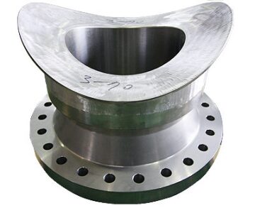
Self-reinforced forged nozzles are nozzle necks that have extra wall thickness which avoids the needs for a reinforcing pad, and hence reduces the number of welds to the shell. The ones shown here are supplied by CHW Forge, India. Self reinforced nozzles are advisable at high temperature (>370°C), high pressure (>70 bar), H2 service, low-alloy steel (Cr-Mo) vessels, wall thickness >50 mm, to reduce the number of welds to the shell.
Long welding neck flanges are self-reinforced nozzles integral with a flange. They are often required in client specifications for 2 in. and below.
Self reinforced nozzles with lips are butt-, instead of corner-, welded to the shell, allowing control of the weld by RT. They are the ultimate type of nozzles and are often requested by clients for lethal service. Pay attention, they cost a fortune and impact the schedule.
Scope of supply
All welded internals shall be included in the vessel supplier’s scope supply. For removable internals, it is different. Standard internals, whose type is defined by the purchaser, such as coalescer, mist eliminator, packing, and catalyst support (wedge wire screen), are best included in the scope of supply of the vessel vendor to prevent interface and guarantee issue.
Non-standard internals, including trays, packing, distributors for columns, filter elements (cartridges), which are not standard but specifically designed to meet the process requirements specified on the process data sheet for internals, are best excluded from the scope of supply of the vessel vendor and purchased separately. This enables direct contact and selection of these internals, critical to the process performance, by the purchaser.
This, however, creates an interface issue as the trays/packing weight and loads have a major impact on the vessel wall thickness. It is therefore highly recommended to obtain weight/loads form the internals vendor and advise the same to the pressure vessel manufacturer before the purchase order, so that the latter can consider the same in the design, avoiding a claim.
Internals shall therefore be selected/ordered early, preferably before the vessel itself. Another recommendation is to have a representative of the internals vendor attend the kickoff meeting with the vessel manufacturer.
The design of the welded supports of these free issued internals shall be part of the internals vendor’s scope of work.
To prevent such interface issues, it might be possible to keep the supply of special internals in the vessel supplier’s scope as nowadays many reputed suppliers do vessel design and fabrication along with design and supply of internals as a complete package.
It shall be specified that removable internals are designed to pass through the vessel manhole(s) and allow easy installation and removal.
Filter vessels shall not necessarily be purchased from manufacturers of filter elements. It is economical to purchase only the design (number of filter elements hence diameter of the vessel) and the filter elements from the latter and to purchase the housing (filter vessel) including the tubesheet for filter elements separately.
The filter housing manufacturer requires the number, size, and weight of filter elements. It shall therefore be communicated prior to the purchase order. It is obtained from the filter vendor upon issue of the process data sheet showing the filter functional requirements: filter type, service conditions, required performance, maximum pressure drop, and material.
Include clips on the vessel for supporting platforms, pipes, heat insulation, and fire proofing inside the scope of supply, but leave these items themselves outside.
The vessel supports (skirt/saddles/lugs/legs) are designed by the vendor along with the number, position, and sections of anchor bolts (no need to specify this as the vendor needs to do it as part of its mechanical design for seismic and wind loads).
Shipping saddles may be included in the scope of supply for large columns/vessels in addition to service/original supports to mitigate shipping/transportation loads.
Some client specifications call for skirt support to be a forged ring type or weld buildup, instead of just filled weld, for heavy-wall (defined as thickness >1.5 in. or >2 in.) vertical vessels. This is only justified in case of the repeated thermal stress due to transient loads.
Anchor bolts themselves do no need to be supplied by the vendor.
For large/heavy vessels, include a foundation template in the scope of supply. It is a ¼-in.-thick steel or wood plate that matches the actual equipment anchor bolt positions. This template shall be delivered at the installation site ahead of the vessel. It allows the civil contractor to cast the foundation, with accurate bolts position, ahead of the vessel delivery to save time. If no such template is provided, the civil contractor will wait for the vessel delivery to check the position of anchor bolts before casting the foundation. Indeed for large/heavy vessels, the base ring does not provide much allowance for out-of-tolerance bolt positions. The foundation template is a key component and great schedule improver in onshore applications.
Vendor references
Pressure vessels manufacturers are usually qualified and regularly weld carbon and stainless steel. This might not be the case of other materials (high nickel steel, etc.) or special processes (clad). If a welder has not used a specific welding process in the last 6 months, the ASME code requires the welder to requalify. Therefore, when preparing your bidder’s list, call around to find suppliers who regularly weld this type of material as evidenced by recent deliveries.
Vendor documentation
The VDRS (Vendor Data Requirement Schedule) is issued as part of the vessel inquiry. It shall include the following design and fabrication documents, to be submitted by the purchaser. All documents issued shall be signed as checked. If a document has not been signed as checked it shall be returned as incomplete.
These documents shall include at least the following:
- Outline and general assembly drawings that show all design basis and vessel data.
- Detailed drawings
- Installation, operation, and maintenance manual
- Welding documents to include at a minimum a weld map, welding procedures specification, and procedure qualifications
- Fabrication procedure to include at a minimum forming procedures for shell and head plates, post-weld heat treatment procedures, non-destructive testing procedures, and pressure test procedures
- Manufacturer data report. On completion of the vessel, the manufacturer shall issue a form X conforming to the code in order to certify that the vessel has been designed, constructed, and tested in every respect in accordance with code. This form X shall be countersigned by the inspection authority.
- Guarantees. The manufacturer shall guarantee the mechanical, design, and workmanship in the construction of vessels. When internals are included in the scope of supply, the supplier shall guarantee the process performance.
Shipping
Take into account the location of manufacturers, which affects delivery time and shipping costs. Shipping of large-diameter (above 4 m) vessels can be a challenge and add to the cost and time because of road permits, requirement to ship by river when not feasible by road, etc. For such vessels supplied from vendors whose facilities are not near the sea, it is a good idea to ask the supplier, who knows the local transport restrictions, to quote free on board (FOB) related to an international port. For long-lead items, the required delivery time, consistent with project time schedule requirements, shall be specified in the inquiry.
Engineering drawing
Pressure vessels can be ordered either on the basis of a process data sheet, including a skeleton drawing or on the basis of an engineering (guide) drawing.
Skeleton drawing:
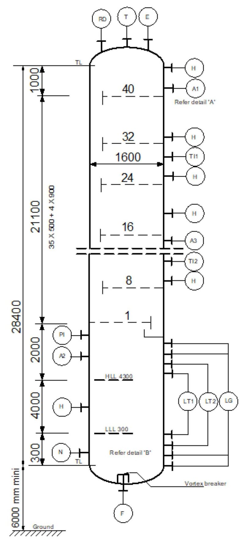
Engineering drawing:
The engineering drawing sets the vessel/plant interface data, i.e., the position "elevation + orientation") of the nozzles and manholes, which allows the plant design to be developed around the equipment (design of access platforms, routing of connecting pipes).
It is not necessary for the purchaser to perform the mechanical design of the vessel, i.e., to define the materials and calculate the thickness of the vessel parts. The mechanical design only has a minor impact on the interface data (the position of welds might require some slight changes of nozzle/manhole position).
The exact position of nozzles is only required at the final design stage to issue piping isometrics. It will be obtained from the manufacturer's general arrangement drawing.
Mechanical design
The mechanical design of the vessel is best left to the equipment vendor. The wall thickness of every part of the vessel is calculated so that the stress under the combined loads does not exceed the allowable stress for the material. Loads include internal pressure, external pressure (for vessels operating under vacuum conditions), wind, seismic, blast loads, forces from connected pipes, self-weight, and weight of contents. Calculations are normally done using third-party commercially available software that includes code formula and material properties.
Performance guarantee/mechanical warranty
As the design of pressure vessels is done by the purchaser, no performance guarantee is requested from the vendor but only a mechanical warranty, covering the 3 “Fs”: faulty (mechanical) design, faulty material, faulty workmanship.
References
Pressure Vessel Handbook, 14th Edition, E.F. Megyesy, Pressure Vessel Publishing.
Pressure Vessel Design Manual, 4th Edition, D.R. Moss, Gulf Publishing.
Practical Thermal Design of Shell-and-Tube Heat Exchangers, 1st edition, Rajiv Mukherjee, Begell House.
Practical Thermal Design of Air-Cooled Heat Exchangers, 1st edition, Rajiv Mukherjee, Begell House.
Author bios: Navid Tajik, Sagar Gaikwad, Mansour Hamza, Marco Garofanello, VU Nathan, Rajiv Mukherjee, and Hervé Baron
To download this article as a pdf, click here.