
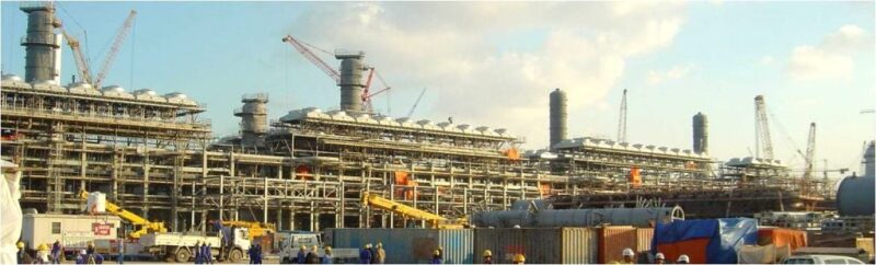
The majority of mechanical equipment found in oil and gas facilities belongs to the static equipment group, which comprises pressure vessels (drums, columns, reactors, filters) and heat exchangers (shell and tubes, plate and frame, air coolers).
A previous article presented guidelines for cost-effective recommendations for the equipment’s design, materials, and fabrication. Its goal was to enable the project engineer, who is not an equipment specialist, to check that economical choices are made across all involved disciplines.
This article has the same goal for heat exchangers: to make sure that across all disciplines involved—process, heat exchange, and mechanical—the most cost-effective choices are made.
Many a time one discipline is not fully aware of the cost impact of what it specifies. It is also common for a discipline to go beyond a functional specification, making a selection instead, and thus depriving the project of a more economical selection down the line.
The first part of this section is common to all types, followed by sections that are specific to each type of heat exchanger.
Process Input Data
On top of the data required for pressure vessels, the following shall be specified by process:
- Names of flowing streams, their inlet/outlet temperatures, and physical properties (density, thermal conductivity, viscosity and specific heat) at inlet and outlet temperatures
- In a case of a fluid condensing or vaporizing: heating/cooling curves showing how the heat duty and vapor mass fraction vary with temperature, and the corresponding thermal properties of the liquid and vapor fractions
Note that the mechanical design of the heat exchanger shall consider all possible operating cases. There could be operating cases at low turndown where the thermal expansion is increased, compared to the design case, due to increased cooling on the process side. The process data sheet shall therefore include the extreme operating cases, including the turndown case.
Overdesign
An overdesign margin, i.e., excess heat exchange surface area, is provided to account for possible inaccuracy of the process data as well as possible plugging of tubes. As described hereinafter, the process discipline usually performs the thermal design of shell and tube (S&T) heat exchangers. It therefore includes such overdesign, commonly 10%, in the design. For the other types of heat exchangers, the overdesign margin shall be specified by type of process. Please refer to the specific sections hereinafter for guidance.
Types of Heat Exchangers
There is quite a large choice in types of heat exchangers: S&T air-cooled heat exchangers (ACHE), pipe-in-pipe/hairpin, and plate and frame (P&F) are the most common. Other compact design exchangers like semi/fully welded plate exchangers, printed circuit heat exchanger, shell and frame exchanger, etc., are getting popular due to their compact footprint and weight which makes them very popular offshore.
The type of heat exchanger is indicated by process on the process data sheet. Because the process engineer is not often familiar with the cost of each type, an uneconomical selection may be made.
When energy savings is required, an exchanger, typically a feed/effluent exchanger, a steam generator, or a boiler feedwater preheater is used.
When cooling only is required, water is used wherever available. In case cooling water is not available, e.g., in desert areas such as in the Middle East, or if it is so corrosive that its use would result in the requirement for expensive corrosion-resistant materials, only ACHE are used.
ACHE have a much lower heat-exchange coefficient and are much more expensive than water-cooled exchangers on an initial cost basis. However, they are very economical on a total cost basis, as they eliminate the high cost of handling cooling water.
When winterization is required, i.e., when the minimum air temperature could cause the process fluid to freeze, selecting ACHE adds to the cost due to the heating coils, recirculation, and louvers required for their winterization. Finally, an ACHE can usually cool down economically to the air temperature +10°C only (compared to +5°C for a water-cooled exchanger). In addition, air-supply temperature is always greater than water-supply temperature.
A combination of air-cooling followed by downstream water (called trim) cooling is standard. For instance, at a plant site where the air design temperature is 40°C, cooling down to 55°C will be by air cooler and further cooling by water cooler. The term process outlet temperature breakpoint is used for 55°C. It is usually 15°C above the ACHE air design temperature. The choice is usually made by the client and indicated in the design basis.
Air coolers have a significant impact on the layout of the plant. Indeed they cannot be located above any facility due to the air draft they induce. They are usually installed on top of pipe racks.
To download this article as a pdf, click here.
Plate and frames (P&F), also called plate heat exchangers (PHE), are far more compact than S&T. Their heat transfer coefficient is much greater so that the surface is much reduced. They can be cost-effective, in particular in cases where expensive materials of construction (alloy) are required.
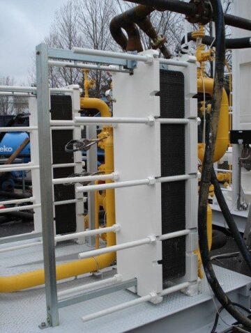
There are two types of P&F heat exchangers: gasketed and welded. The gasketed type is the cheapest. It is usually limited to a design pressure of 25 bar g and a design temperature of 185°C. Expanding the heat exchange duty of this type of heat exchanger at a later date is very easy by adding plates in the frame.
P&F heat exchangers are also considerably more compact than equivalent-duty S&T. A P&F exchanger occupies about 15% of the plot area of an S&T heat exchanger (and only 11% considering the area required for maintenance, i.e., removal of S&T heat exchanger bundle).
When low-duties are concerned, pipe-in-pipe or hairpin-type heat exchangers are sometimes specified. Nevertheless, due to a restricted number of suppliers, they are not competitive compared to S&T heat exchangers with U-tubes.
Spiral heat exchangers (SHE) should also be considered for severe fouling service due to the high turbulence created by the continuous change in flow direction minimizing fouling. This type of heat exchanger is also quite compact but not to the same extent as PHE. They can handle design pressures up to 25 bar g and design temperatures up to 400°C, as they have conventional gaskets. Thus, the applicability of SHE is much wider than that of PHE.
There are also some heat exchangers such as MCHE—main cryogenic heat exchangers (coil-wound), plate and fin, printed circuit heat exchangers (PCHE) for very compact, high-pressure, multiple-process stream into a single unit, variable temperature service, close temperature approach, etc., with proprietary licensor/vendor design, highly efficient for specific applications such as LNG, refining, etc.
Offshore, where the equipment footprint and weight are critical, PCHE are selected nowadays. For example, in a typical application, a 100-ton S&T heat exchanger was replaced with a 15-ton PCHE with installed cost saving of more than $10 million.
Fouling Resistance
Fouling is the deposition of undesirable matter on the heat exchange surface, which reduces the heat exchange. This is an extremely important parameter of an exchanger design. A higher fouling resistance translates into a reduced heat transfer. The purchaser must specify the fouling resistance. Use plant operating experience or, by default, the values given by the Tubular Exchange Manufacturing Association (TEMA) for the different types of fluids.
Fouling Layer Thickness
Heat exchangers experience more pressure drop as they get fouled due to a reduction in the area of the flow passages. While fouling resistance is considered by almost all designers to account for the loss in heat transfer, very few of them consider fouling layer thickness to account for the higher pressure drop. This is highly anomalous because the deposit comes first and then, as a consequence, the thermal resistance. For dirty and viscous fluids, the fouled pressure drop in a heat exchanger can be up to three times the clean pressure drop, both inside and outside tubes. Keeping velocities high enough to avoid deposits, avoiding stagnant region/hot spot/cold spot are mitigation measures in heat exchanger thermal design. In the HTRI software, fouling layer thickness can be entered directly.
Hairpin Heat Exchangers
For low duty, below 500 kW, where the diameter of a S&T heat exchanger would be below 200 mm, hairpin heat exchangers might be a good choice. They come as single tube (double pipe) or multiple tubes within a hairpin shell (multitube). It is best not to specify double pipe or multi tube and leave it to the vendor to optimize. Hairpin heat exchangers come with U-tubes, straight tubes (with rod-thru capability), fixed tubesheets, or removable bundle.
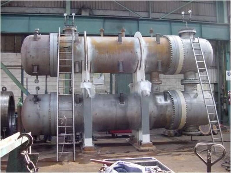
Shell and Tube Heat Exchangers
Fluid sides
- The process data sheet indicates which fluid is on the tube side and which fluid is on the shell side. Check that the allocation is sound.
- The highest-pressure fluid shall be on the tube side to minimize the impact of pressure on wall thickness, hence material cost.
- A fluid with tendency to foul should also be put on the tube side, which is easier to clean: Cleaning the inside of (straight) tubes is easier than cleaning the shell/outside of the tubes
- A corrosive fluid should be put on the tube side in order to minimize the amount of expensive corrosion-resistant material used.
- A fluid with low pressure drop available shall go on the shell side.
- Fluids with vapor phase should be on the shell side because it provides larger volume to suit its lower heat transfer coefficient.
- Fluids with high temperature difference across one pass shall be located on the shell side to reduce the axial compressive tension and avoid the expansion joint.
- Toxic or lethal fluids should be on the tube side.
Exception: The above factors are the major variables in decisions making. They may, however, have effects on each other and make the fluid allocation more complicated.
Design code
ASME BPVC Section VIII–Rules for Construction of Pressure Vessels Division 1 applies to S&T heat exchangers, as these are pressure vessels. On top of that, API 660, and TEMA, specific to S&T heat exchangers, are usually applied. In the European market, PED (Pressure Equipment Directive) requirements are mandatory, designed for either EN code or ASME code.
TEMA has different classes: TEMA C (General Service) is less stringent than TEMA R (Refinery service). TEMA C is the most cost-effective. It is appropriate for machinery auxiliaries, e.g., lube oil, at low to moderate pressure and temperature. TEMA R is the standard for process exchangers in the oil and gas industry.
Generally, shell-side pressure of 300 bar, tube-side pressure of 1400 bar with temperature range of (−)100°C to (+)600°C are limitations for S&T exchangers.
Shell-side design pressure
It is usual to find large differences of pressure on tube and shell sides. The typical case is cooling of high-pressure gas in the oil and gas industry, with low-pressure cooling water on the shell side. Tube rupture is usually considered as an accidental case. The shell side should be protected from the resulting overpressure event. This could be achieved in two ways:
- Addition of a pressure relief device on the shell side, usually a rupture disk as a pressure safety valve is not fast enough
- Increase the shell-side design pressure up to 10/13 of the tube-side design pressure. (The logic behind this “10/13” rule is that the hydrotest is done, as per ASME, at 1.3-times the design pressure—it was popularly known as the ⅔ rule based on old code hydrotest pressure before the year 2000).
For pressure up to the limits of Class 150 lb, select option No. 2. For higher pressures, review case by case. Dynamic simulations are performed for more accurate pressure safety value sizing for tube rupture scenarios than steady-state methods for differential pressure over 70 bars when the lower pressure inside is not protected by the 10/13 rule.
Allowable pressure drop
The pressure drops permitted by the systems affect heat exchanger size.
Higher allowable pressure drops result in a reduction in the heat exchanger size, but increase the operating cost due to the additional pumping power. Thus, the total cost of the heat exchanger should be minimized considering both aspects.
Thermal design
The thermal design of S&T heat exchangers has to be done by the purchaser, as the suppliers, who are pressure vessel manufacturers, do not usually have the skills to perform thermal design. Some do and offer a thermal guarantee, on top of the mechanical warranty at a premium cost and delivery schedule. The purchaser performs the thermal design using publically available thermal design software.
Vibration analysis
S&T heat exchangers are subject to flow-induced vibration, due to unsupported tube lengths subjected to high flow rate on the shell side, which could result in tube failure.
A vibration analysis should be done. The simplified TEMA method is now archaic. HTRI's Xist is the standard software used for thermal design of S&T heat exchangers. It carries out sophisticated vibration analysis measures such as double segmented baffles, NTW (no tubes in window), inlet support baffles, impingement rods, patented tube support devices, etc. (The quote of a particular make of software made here is without any commercial intent, but simply reflects the current practice and recommendation).
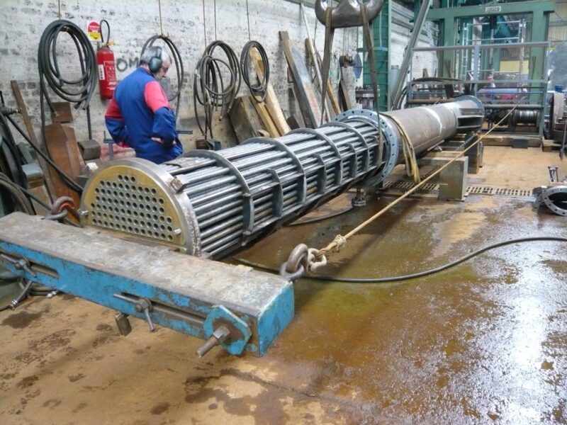
Types of S&T heat exchangers
S&T heat exchangers come in a number of subtypes, referred to by three letters according to the TEMA standards such as “AES” or “BEM.” The first and the third letters refer to the type of the front and rear heads, while the middle letter, which is the shell type, is crucial for thermal design. It defines the flow pattern of the shell-side stream through the exchanger.
Several factors come into play in the selection of heat exchanger type, including mechanical, thermal, and ease of maintenance , i.e., chemical/mechanical cleaning considerations. The choice is between removable bundle or not, straight or U-tubes, and type of heads—dished end or flange, and is made on the basis of whether one or both fluids are fouling or not.
Whenever not specified in the design basis, fluids with fouling resistances of 0.0004 hr.m2 °C/kcal or greater shall be considered as fouling.
In case none of the fluids is fouling, the most economical type, NEU, with fixed tubesheet and U-tubes shall be selected.
In case only one of the fluids is fouling, BEM-type with fixed tubesheets welded to the shell and straight tubes is the most economical. The fouling fluid shall be on the tube side, which can be mechanically cleaned, as the tubes are straight. As fixed tubesheets do not allow differential thermal expansion between the tubes and the shell, the temperature difference between the fluids should generally not exceed 50–60 degrees.
This also depends upon whether the tubes and the shell have the same or different metallurgies, as the coefficient of thermal expansion varies between different materials.
Above 50–60°C an expansion joint would be required on the shell, which increases the cost and is a source of leakage over time and may result in a plant outage. It is therefore advised to only consider an expansion joint at low shell-side pressure and for pipe-size shells. If this is not the case, a U-tube removable bundle (BEU) should be selected. The fouling fluid shall be switched to the shell side. In case both fluids are fouling, both straight tubes and removable bundles are required, hence the most expensive floating-head (AES) type has to be selected. This type has the most maintainability and access to both sides; meanwhile this configuration demands the most forging and sealing surfaces, and the most machining or grinding surfaces. The consequence of having the highest number of removable parts is that it is also the most expensive.
AET, pull-through type, allows the bundle to be pulled without disassembly of the floating head. However this requires a high clearance between the bundle and shell resulting in a large bypass area. Select AET for large-diameter shells (>800 mm). For lower-diameter shells, use AES type, i.e., using split flange head backing device.
The heads shall be selected in an economical way. Use of a bonnet (dished) head is more economical than a channel (flange). However bonnet types require dismantlement for cleaning, disturbing the piping connections. Make a choice on the basis of fouling of the tube-side fluid. Select A (flanged) type when fouling and B (bonnet) type when tube-side fluid if not fouling, and for hydrogen or toxic service.
Maximum size
It is usual to limit the diameter of the shell for floating type head (60 in.) to 1500 mm and the tube length to about 8 m to 9 m in order to limit the weight of the bundle to 20 tons for handling during maintenance. For fixed head and U-tube, range of 2 m dia × 12 m bundle length may be adopted. In offshore oil and gas platforms, tube length is limited to 6 m for easy handling.
Standardization
It is a good practice to standardize the tube size, thicknesses, and lengths to a few values to limit the amount of spare tubes to stock for repair. In some cases even the removable bundles could be standardized for multiple exchanger services.
Tubesheet design
ASME and TEMA give two different ways of calculating the tubesheet thickness. TEMA’s calculation is less sophisticated than ASME’s as it does not take into account the rigidity provided by the shell and the stationary head. ASME checks main-shell and channel-shell junction stresses, which are not covered in TEMA and, in most cases, govern the tubesheet thickness. Therefore, the tubesheet thickness as per ASME is always higher than TEMA. It is therefore important to specify if the tubesheet thickness shall be calculated as per ASME or TEMA.
In case of high pressure, e.g., in-line waste heat boiler such as the one used in Claus units, the thickness of the tubesheet is calculated using ASME I instead of ASME VIII to reduce the thickness. ASME I considers that the tubesheet is stayed by the tubes, which is not the case of ASME VIII.
Extended/confined tubesheet
For removable bundles type, the tubesheet might be confined between the shell and channel flanges and does not need to be extended to have an outer diameter (OD) equal to that of the channel flange with collar bolt design. This is not requested by the codes (API 660 or TEMA). It might be requested by some clients to facilitate hydrotesting of the bundle outside the shell. Do not ask for it unless it is mandated in the client specification.
Impingement protection plates
When the impact factor exceeds the TEMA limits, impingement protection is required. The TEMA standards specify different rho-v-2 limits for erosive fluids and nonerosive fluids. Impingement plates have to be provided for two-phase streams. Circular or rectangular impingement plates are commonly employed, but impingement rods are now becoming more popular as they minimize the potential for flow-induced vibration.
Tube-to-tubesheet connection
The tube-to-tubesheet connection is the subject of much theoretical discussion.
The practical and proven way to ensure mechanical strength is to expand the tubes into groove(s) in the tubesheet: a single groove for tubesheet thickness below 1 in. and two grooves above.
If leak tightness is required, for instance to avoid cross-contamination of tube- and shell-side fluids, a (seal) weld shall be added.
The API code and some client specifications call for strength welds; replacing the tube expansion into grooves + seal weld by combining both mechanical strength and leak tightness is a weaker solution and is not recommended.
Tubing
This can be a significant cost element when ordering large heat exchangers. Heat exchangers use tubing as tubes.
Tubing is specified based on OD. The most popular tube sizes are 3/4 in. and 1 in. These sizes give the best all-around performance and are most economical in most applications. Smaller sizes would be difficult to clean and larger sizes are used only in pressure-drop-limiting situations. Smaller-diameter tubes should be preferred when the tube-side design pressure is very high, in order to reduce the tube thickness.
Stick to the standard tube size, length, and wall thickness as indicated in TEMA.
A low or even zero corrosion allowance is taken into account for tubes as they are considered a replaceable component of the exchanger. Tube thicknesses indicated in the TEMA standards have two components: one toward strength and the other toward corrosion. Since these components are not indicated, engineers generally think that tubes do not have any corrosion allowance. However, if a fluid is extra-corrosive, a higher tube wall thickness should be selected. It is the responsibility of the purchaser’s materials specialist to specify the tube thickness.
Either tube minimum or average wall thickness is specified. Tubes specified with average wall thickness are cheaper. Stick to average wall thickness unless high pressure, corrosive, or client specification mandates otherwise.
Do not impose seamless tubes, which may cost more and have longer delivery. Welded tubes, which undergo a greater amount of non-destructive evaluation, are just as reliable and have a more consistent wall thickness. However when cost difference is not significant, prefer seamless tubes for a long life cycle of exchanger bundle.
Tube pattern
There are triangular or square tube configurations. A triangular configuration allows the fitting of 5–10% more tubes within the same shell inner diameter but makes shell-side cleaning difficult. Select a square configuration or large-tube pitch when shell-side cleaning is required. It is therefore very common to have triangular pitch in fixed tubesheet exchangers and square or rotated square pitch in U-tube or floating-head exchangers. Whether square or rotated square pitch should be used depends upon the degree of turbulence on the shell side. Where this is low, as is the case with viscous liquids, a rotated square pitch yields a much higher heat transfer coefficient for the same pressure drop. The type of cleaning method (chemical/mechanical) adopted by the client also drives the pitch selection.
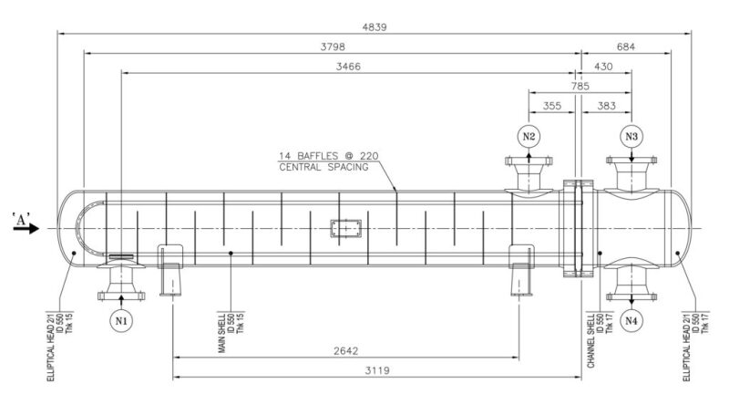
Engineering drawing
A sketch such as Fig. 1 can be extracted from the thermal design software, showing equipment dimensions. It also indicates equipment weight, positions of nozzles and supports. However, such information is not accurate and does not allow equipment integration engineering (i.e., design of equipment foundation and connecting piping), to proceed.
Indeed the mechanical design must be performed to determine the equipment weight, the position of supports as well as that of nozzles, which depends on the thickness of flanges, positions of welds, etc.
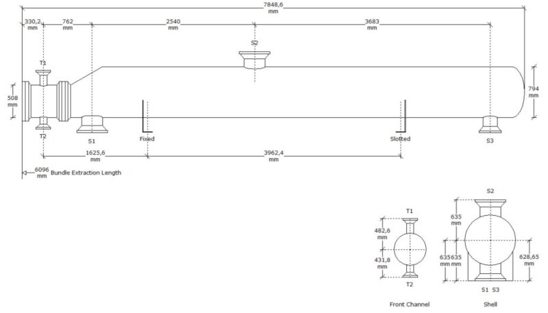
Upon completion of the mechanical design, the engineering drawing required for equipment integration engineering, which shows the interface data (equipment dimensions, loads, nozzles, and supports positions) can be produced.
Materials
A heat exchanger uses a variety of materials due to the different natures, states, temperatures, and contents of corrosive components of the fluids on shell and tube sides. Galvanic corrosion and prevention of erosion shall be governing considerations. Velocity limitation (both minimum and maximum), cladding of interface of bi-material connections, shall be reviewed, etc.
Performance guarantee/mechanical warranty
Even though in most of the cases the thermal design of S&T heat exchangers is performed by the purchaser, the mechanical design might affect the thermal performance. Both the mechanical design and thermal design shall therefore be the responsibility of the supplier when both guarantees are to be given, which, as stated above, comes with some premium cost.
Rule of Thumb in Costing
S&T heat exchanger geometry has a direct impact on the cost. Long and small-diameter exchangers are the most economical. Considering 30 bar design pressure on both sides, a 1.5 m shell dia x 3 m tube length (3,000 tubes) exchanger will cost twice as much as a 0.3-m shell diameter x 8-m tube length (500 tubes) exchanger, both exchangers having the same heat exchange area.
For carbon steel S&T heat exchangers, the equipment cost can be estimated using the rule of thumb of $500/m2 of heat exchange area.
Reference
Profiles of the authors can be found here: Navid Tajik, Sagar Gaikwad, Mansour Hamza, Marco Garofanello, VU Nathan, Rajiv Mukherjee, and Hervé Baron
To download this article as a pdf, click here.