
The most common method used for the placement of cement plugs is the balanced-plug method using drillpipe, tubing, or a combination of both. A stinger with a smaller diameter than the drillpipe is commonly run on the bottom of the drillpipe for setting a balanced plug. However, a mathematical analysis of what occurs once dynamic conditions are initiated by pulling out of hole (POOH) with a small-diameter stinger shows that the initially balanced system quickly becomes unbalanced.
Introduction
The balanced-plug method of calculating plug-placement volumes has long been a standard industry practice for setting plugs in the wellbore. Volumes are calculated in such a way that all fluids both inside and outside of the pipe are at the same height, thus resulting in a hydrostatically balanced system.
The basic assumption behind the balanced-plug calculation method is that the fluid is going to remain in place while the drillpipe is simply pulled through the fluids with minimal falling of the fluid level to fill the void left behind by the metal displacement of the drillpipe. This assumption is correct, neglecting the frictional drag forces on the fluid, when the drillpipe outer diameter (OD) and inner diameter (ID) are the same from top to bottom. However, when the drillpipe includes a stinger at the bottom, there is a disruption in the hydrostatic equilibrium between the column of fluid inside and outside the drillpipe, resulting in flow at the bottom of the stinger between the two regions.
As soon as this dynamic situation is imposed on the fluids in the wellbore, the fluids downhole begin to experience a continual shifting in hydrostatic conditions. When a stinger is used at the bottom of a larger-diameter drillpipe, the difference in volumetric capacities per annular length can be substantial. The difference in the volumetric capacities inside the pipe per length can also be substantial. As a given length of larger-diameter drillpipe is pulled out at surface, all the fluid that was contained within that drillpipe, and the fluid in the annulus that was surrounding it, will attempt to stay in place. As noted earlier, there will be some drop in the fluid level caused by the removal of the volume of steel in the drillpipe. However, a much longer length or column height of fluid per unit volume is displaced within the smaller--diameter stinger because of its smaller capacity. After pulling out several hundred lineal feet of drillpipe at the surface, a substantial difference in lineal footage of fluid has passed through the stinger. If these fluid-column-height changes are not taken into account in the placement calculations, as they are not in the balanced-plug method, the result will be a plug that has had other displacement fluids dumped into the middle of the cement as the drillpipe is pulled out of hole.
Dynamic Conditions When Using a Stinger
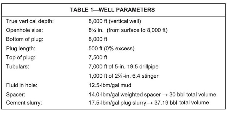
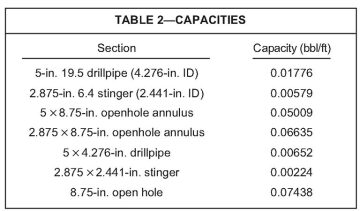
One can assume a very simple open system in a vertical wellbore with parameters and volumetric capacities detailed in Table 1 and Table 2, respectively. Note that this scenario places all of the spacer and cement in the stinger/openhole annulus. Having fluids of different densities above the drillpipe/stinger interface would only further complicate the balancing of the system while POOH. The assumption is made that fluid within the drillpipe has only two possible places to go: down and out the bottom or spilled out on the rig floor at surface. The balanced-plug method would yield the following conditions:
- Top of cement with drillpipe in place: 7,484.46 ft
- Top of spacer with drillpipe in place: 7,068.57 ft
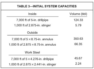
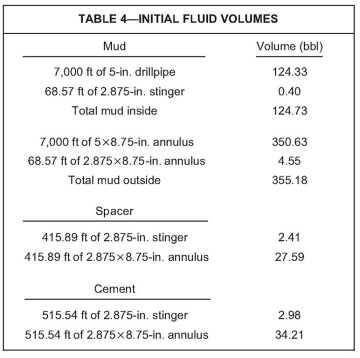
The capacities within the system are described in Table 3, and the individual fluid volumes within the system are provided in Table 4.
Next, a look at the well conditions after pulling out 100 ft will be observed. A common industry misconception is that it will be assumed that all fluids will remain effectively in place while the drillpipe and stinger simply pull through the fluids. The only change made to the volumes within the system will be the loss of 100 ft of 5×4.276-in. steel that was pulled out of the well. This results in a loss of 0.65 bbl of volume. In a balanced system, the level of fluid remains the same inside and outside of the drillpipe. The volume of steel removed from the wellbore would cause the fluid level to drop 9.61 ft below the surface both inside and outside the drillpipe. Working from the inside of the drillpipe top to bottom and referencing the fluid volumes of the original placement conditions given previously, the shift toward hydrostatic imbalance can already mathematically be seen.
The new fluid volumes within the system after POOH 100 ft are as follows. The 124.73 bbl of mud inside the system has remained unchanged. The fluid level has fallen 9.61 ft because of the removal of the drillpipe. By starting at the top and working down through the tubulars, we can mathematically calculate how the fluid interfaces have transitioned after POOH 100 ft. Starting at 9.61 ft and working down, the base of mud/the top of the spacer can be found. (For the corresponding equation for this calculation, as well as specific equations involved in other calculations in this work, please see the complete paper.) The remaining volume must push down into the 2.875‑in. stinger. The base of the mud/the top of the spacer has moved from being 69 ft below the drillpipe/stinger interface initially to now being 407.60 ft below the drillpipe/stinger interface.
The volume and length of spacer inside the drillpipe remains unchanged, with 2.41 bbl continuing to occupy 415.89 ft of the 2.875-in. stinger. However, because the mud/spacer interface has pushed farther down the drillpipe, the spacer/cement interface has also pushed farther down. The new spacer/cement interface is 415.89 ft below the mud/spacer interface at 7,307.60 ft. This leaves the bottom 176.51 ft of the stinger that is filled with cement.
With all fluid volumes and levels inside the pipe accounted for, the lengths of fluids outside the pipe can now be determined, starting from the bottom of the stinger and working back up to the surface. The volume of cement in the system is 37.19 bbl. 1.02 bbl of that was determined to still be inside the 2.875‑in. stinger. The remaining 36.17 bbl of volume will occupy the 100 ft of 8.75‑in. open hole that is now free of any type of tubular, and the rest will fill the 2.875×8.75-in. annulus.
The volume and length of spacer outside the drillpipe remains unchanged, with 27.59 bbl continuing to occupy 415.89 ft of 2.875×8.75-in.-annulus length. However, because the cement/spacer interface has pushed up the annulus because of the fluids that have exited the drillpipe and stinger, the spacer/mud interface has also pushed up. The new spacer/mud interface is 415.89 ft above the cement/spacer interface at 7,469.56 ft.
The remaining annulus from 7,051.10 to 9.61 ft from the surface will be filled with mud. Table 5 summarizes the new fluid levels. By simply comparing the heights of each fluid in Table 5, it becomes very clear that the system is not balanced. A quick calculation of the hydrostatics concludes that the system is now underbalanced by 67 psi inside the drillpipe. In order to balance, the fluids in the annulus must fall, pushing heavier cement back into the stinger, spacer farther up the stinger, and mud up and out of the drillpipe until equilibrium is reached. For balance to be achieved, the fluid in the annulus would have to fall to approximately 29 ft below the surface.

Balanced Plug
These calculations show how quickly such a dramatic change is imposed on the system and how the drillpipe is not simply pulling straight through the fluids, leaving them undisturbed. By continuing with these same analytical assumptions farther up the hole, the system will soon reach a point at which all cement has exited the inside of the stinger while several hundred annular feet of cement remains outside of the stinger. At this point, spacer will begin to exit the stinger and dump into the middle of the cement plug, and once all of the spacer has exited, mud will begin to dump into the middle of the cement plug.
To more accurately assess the conditions of the wellbore while POOH, more iterations need to be calculated. The use of computer software designed to calculate multiple iterations and predict fluid activity while POOH is an excellent option to avoid tedious or complicated hand calculations. By use of such software, a pictorial simulation of this particular well scenario was generated (see the Appendix of the complete paper), pointing to the fact that calculating a simple balanced plug is anything but simple when a stinger is used.
Alternative Options
Eliminating the stinger altogether and using a uniformly sized drillpipe from top to bottom should be an option to consider. The balanced-plug method would then be applicable for calculating fluid placement, which simplifies calculations. This method eliminates the continual fluid movement that occurs while using a stinger, which should in turn lead to a more stable plug while extracting the drillpipe from the cement. These advantages would need to be weighed against the increased column height of the cement with the pipe in place and any potential issues caused by smaller annular clearances.
There are also mechanical devices available that can be placed in the drillpipe immediately above the stinger. These devices allow the cement plug to be balanced using the basic balanced-plug calculations. In addition, an indicator sub can be used to give a pressure indication that the plug has been spotted on depth. After spotting the plug, the stinger is released from the drillpipe before POOH. This eliminates the instability associated with extracting the stinger from the cement plug. In this case, the stinger is abandoned in the well. If it is necessary to drill out the plug, then the stinger would need to be composed of drillable material.
Conclusions
When a small-diameter stinger is in use on the end of the drillpipe, the balanced-plug calculation method for spotting the cement plug will result in contamination of the top section of the plug while extracting the stinger. The contamination can be 40 to 50% of the cement volume. In addition, there is a much higher likelihood of fluid U-tubing out of the drillpipe, resulting in spills on the rig floor. (The calculation method to avoid contaminating the top part of the cement plug and to avoid generating spills on the rig floor is quite complicated and requires the use of a computer application. This type of computer application is currently available to the industry and allows the use of a stinger without sacrificing plug quality.) The balanced-plug calculation method can be used in cases where a stinger is not used, or in cases where a device is run above the stinger to separate the stinger from the drillpipe before POOH.
This article, written by JPT Technology Editor Chris Carpenter, contains highlights of paper SPE 168005, “Don’t Get Stung Setting Balanced Cement Plugs: A Look at Current Industry Practices for Placing Cement Plugs in a Wellbore Using a Stinger or Tailpipe,” by Justin Roye, Schlumberger, and Sam Pickett, Chesapeake, prepared for the 2014 IADC/SPE Drilling Conference and Exhibition, Fort Worth, Texas, USA, 4–6 March. The paper has not been peer reviewed.