
Different subsea-control-system architecture scenarios that could be used to inject CO2 offshore from a carbon capture plant onshore were assessed. Each scenario represented a qualification step toward a minimalist, fit-for-purpose configuration, with the final system featuring simple and all-electric subsea architecture. The authors adopted a holistic approach to a hypothetical subsea carbon capture and storage (CCS) project, evaluating the effect of subsea-control-system equipment technical readiness, CCS regulatory requirements, umbilical sizing, and installation strategy.
Introduction
Experience indicates that one of the more-common types of offshore CCS developments comprises a coastal-based carbon capture and compression plant (generally located in a region with high industrial emitters) and an offshore reservoir selected for CO2 injection, typically a depleted hydrocarbon reservoir or an aquifer, which requires a long tieback to shore, often in excess of 100 km.
Several subsea architecture scenarios were considered, all using a hypothetical CCS development with main characteristics including the following:
- The carbon capture and compression plant is onshore, with the subsea control system located at the plant.
- The five CO2 injection wells are connected to the onshore plant by a CCS flowline in a daisy‑chain configuration by inline tees.
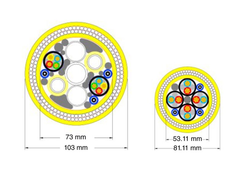
- The subsea control umbilical follows the route of the flowline.
- Subsea injection trees, an umbilical, and a subsea control system were compared.
- The assumed requirements for each CO2 injection well included the following:
- Flowmeter and choke
- Fiber-optic (FO) feedthrough for the distributed acoustic survey (DAS) for CO2 -plume monitoring in the reservoir
- No chemicals required to be injected at the trees for flow-assurance purposes
- Surface-controlled subsea safety valve (SCSSV) leakoff testing (LOT) requirement
The following four architecture scenarios were evaluated:
- Scenario 1—Electrohydraulic controls (traditional subsea production system)
- Scenario 2—Electrohydraulic controls with a common subsea hydraulic power unit (HPU) for valve actuation and LOT
- Scenario 3—All-electric trees with tree-mounted subsea HPUs for valve-leak testing only
- Scenario 4—All-electric trees with valve test downline from a field service vessel (or no LOT)
Scenarios 1 through 3 are detailed in the complete paper; this synopsis concentrates on Scenario 4.
Scenario 4—All-Electric Trees With No Remote LOT Requirements
Scenario 4 represents the optimal architecture. In this scenario, the full system is electrically actuated and the CCS tree has been simplified to achieve an optimized CCS injection cap.