All amines are subject to foaming in industrial applications given certain conditions and circumstances. Methyl diethanolamine (MDEA) is like other types of amine that can experience major foaming upset, especially in high-pressure sweetening units. However, MDEA is one of the most popular solvents for gas treating, with several advantages over other amines, particularly its ability to remove hydrogen sulfide (H2S) and slip carbon dioxide (CO2) from sour gas. This paper describes Saudi Aramco’s efforts to eliminate early foaming incidents during the commissioning stage of the Karan nonassociated (NA) sour-gas field.
Introduction
The Karan field was discovered by Saudi Aramco in 2006. This newly developed offshore field is located 120 km northwest of Jubail Industrial City in eastern Saudi Arabia. Produced sour gas is coblended at a tie-in offshore platform through five 20‑in. subsea flowlines. From the tie-in offshore platform, the gas is sent through a 38-in. subsea pipeline to the onshore gas-treatment facilities at the Khursaniyah Gas Plant. Karan facilities consist of three gas-treatment-processing trains, each designed to process 620 MMscf/D of NA sour gas, producing sales gas and acid gas.
Karan NA sour gas is a CO2-rich stream. Formulated MDEA was selected for sweetening in Karan gas-treating facilities to enhance the H2S/CO2 ratio in acid gas and to meet the required sales-gas specification before sending the gas to the Saudi Master Gas System.
The Problem of Foaming
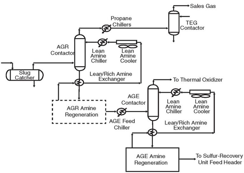
Karan’s three gas-treating trains have a total rated capacity of 1.86 Bcf/D of sour feed gas. Each train consists of an MDEA-based acid-gas-removal (AGR) unit, a triethylene-glycol (TEG) dehydration unit, and an acid-removal (AGE) unit (Fig. 1). In addition, propane is used for process-stream cooling at various points throughout the process, where temperatures of less than 140°F are required. A dedicated propane-compression system runs continuously to cool each process train.

During commissioning of the new trains, a number of foaming incidents occurred in the AGR units. All foaming incidents followed the same sequence, with a gradual temperature increase from 148 to 165°F observed with foaming symptoms. The increase in temperature was followed by a sharp pressure differential across the AGR contactor. This continued to occur although all process parameters were maintained within the design limits and an antifoam agent was being injected during foaming incidents.
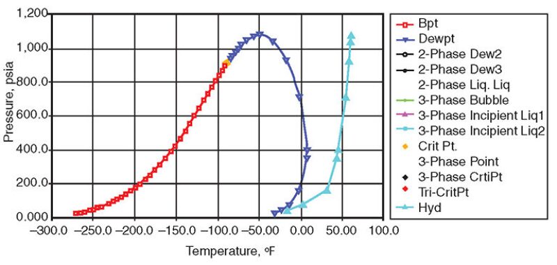
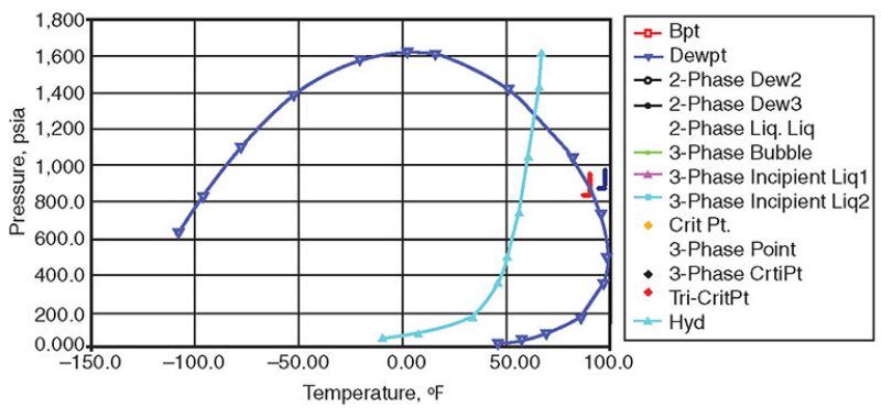
Frequent samples were taken from different locations and sent to an authorized laboratory for analysis. Sample results revealed that Karan feed gas contained heavy hydrocarbon (HC) contents different from the gas compositions specified during the design. On the basis of the actual gas composition, the simulation showed that the HC-phase envelope has shifted dramatically, and the design set points (pressure and temperature), as shown in Fig. 2 and Fig. 3, will promote the formation/condensation of HC liquid in the AGR system. The condensation formed downstream of the inlet positive-crankcase-ventilation unit feeding sour gas to the AGR contactor. In an effort to study the incidents further, operator engineers working with the MDEA vendor simulated the actual feed-gas composition by use of gas processing and conditioning to determine the proper set point on the basis of the actual composition. Some of the process parameters were adjusted, and the major simulation findings are reflected in the following text.


Findings
Sample results showed that the inlet feed-gas compositions are different from the design. The actual feed was 2% higher in heavy HC C6+. Furthermore, the simulated result of the new composition indicated that the design operating temperature will be inside the phase envelope, causing the HC liquid to form, and therefore causing foaming.
Root Causes and Discussion
These findings indicate that the phase envelope dramatically changed, causing the design operating pressure and temperature values to fall inside the two-phase region. This proved that HC-liquid formation/condensation is the primary reason for foaming. Extensive discussions with operator engineering organizations (including process engineering from different gas plants and the MDEA vendor) generated two possible options to diminish the recurrence of foaming and mitigate the HC-liquid impact:
- The first option—which requires major plant modification—was to lower the inlet sour-gas temperature downstream of the sludge catcher to recover heavy HCs, then increase that temperature to a superheated state. This system is called the “dewpoint controller,” and it is used to recover heavy HC liquids. This system is not currently available in the inlet-facility process trains and needs to be evaluated on the basis of a feasibility study.
- The second option was to increase the sour-gas temperature from 91 to 97°F in order to move the operating point away from the HC condensation line of the phase envelope. This option is more practical because it does not include a major system upgrade.
The evaluation showed that the silica--based antifoam agent is compatible yet not recommended, because it accumulates in the system and could create foaming with time. Moreover, the silica-based type could shorten the lifetime of the online carbon bed. A glycol-based antifoam agent was evaluated as a substitute for the silica type and was found to have a slower effect when foaming occurs; however, if it is injected continuously in small amounts it will prevent foaming in the system.
To solve the problem, Karan sour-gas temperature was increased from 91 to 98°F at the inlet of the AGR contactor, and the antifoam agent was changed from silica- to glycol-based. These two steps mitigated the foaming in the AGR contactor. Moreover, all documents were updated to reflect the new operating point (temperature).
Lessons Learned
The plant’s design was based on an inaccurate sour-gas composition, which was obtained only at the early stage of the project. Fortunately, in our case, this small change in the composition was resolved by a minor change in the operating parameter. In other cases, it might require a major design change. It is recommended to take frequent samples from the wells before starting the project proposal.
Taking samples from suspected points and comparing the results with the design are steps required to find the root cause of upsets such as foaming. Moreover, in such analyses, accuracy of laboratory devices is very important, especially when a small change in the composition might change the critical operating point.
This article, written by JPT Technology Editor Chris Carpenter, contains highlights of paper IPTC 17175, “Khursaniyah Gas-Plant Experience With Foaming During Startup of Karan Nonassociated Gas,” by Mohammed Hussain Al-Qahtani, Saudi Aramco, and Paul Garland, INEOS, prepared for the 2013 International Petroleum Technology Conference, Beijing, 26–28 March. The paper has not been peer reviewed. Copyright 2013 International Petroleum Technology Conference. Reproduced by permission.

