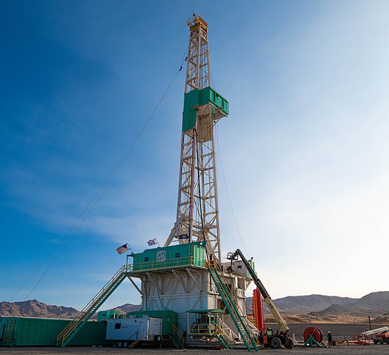
At the Utah FORGE test site, they are drilling wells to try to accomplish something others have failed to in 50 years of trying—inject water into hot rock and produce enough steam to power a commercial electric generator.
There are many reasons why it is hard, particularly finding a way to use fracturing to create what amounts to a slow-moving, high-volume waterflood that heats the water as it flows from an injection well to a production well.
Multiple well pairs per power plant are likely needed, so another problem is finding a way to speed up the drilling, which at the site requires drilling through a mile of granite at temperatures exceeding 400°F.
“This approach will take hundreds and hundreds of wells. The challenge is cost, like in an unconventional well,” said Fred Dupriest, professor of engineering practices at Texas A&M University, while delivering a paper at the recent SPE/IADC International Drilling Conference (SPE 208798).
The comparison to shale is apt because he was brought in at Utah FORGE to teach drillers how to use the hardware and methods that speeded drilling in unconventionals to accelerate drilling through hard rock.
The high cost of slow drilling in hard rock has inspired futuristic ideas such as using plasma energy to disintegrate hard rock. The technology was the basis of a startup, GA Drilling, which was recently bought by Nabors which hopes to commercialize it for hard rock sections.
The challenge faced by Dupriest and his partner on the project, Sam Noynaert, an associate professor of engineering practice at Texas A&M, was to demonstrate that faster drilling methods are possible using available technology.
The future of geothermal energy depends on efforts like Utah FORGE’s, which are funded by the US Department of Energy (DOE), to overcome the subsurface barriers that have limited geothermal power to less than 1% of the US electric supply.
Growth has been limited by the available resources. There are so few places in the US or the world that combine geothermal heating, water, and naturally conductive fractures that make it possible to drill wells that produce superheated steam.
On the other hand, it is not hard to find hot, dry rock. If profitable systems can be built to inject the water into hot formations and produce enough very hot water, geothermal power plants could be located near big, urban power markets.
Bits and Brainpower
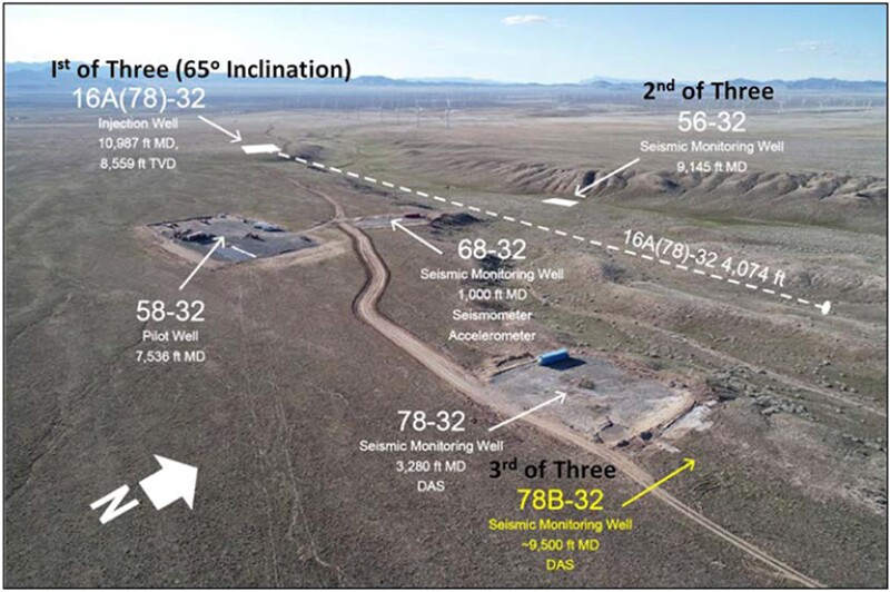
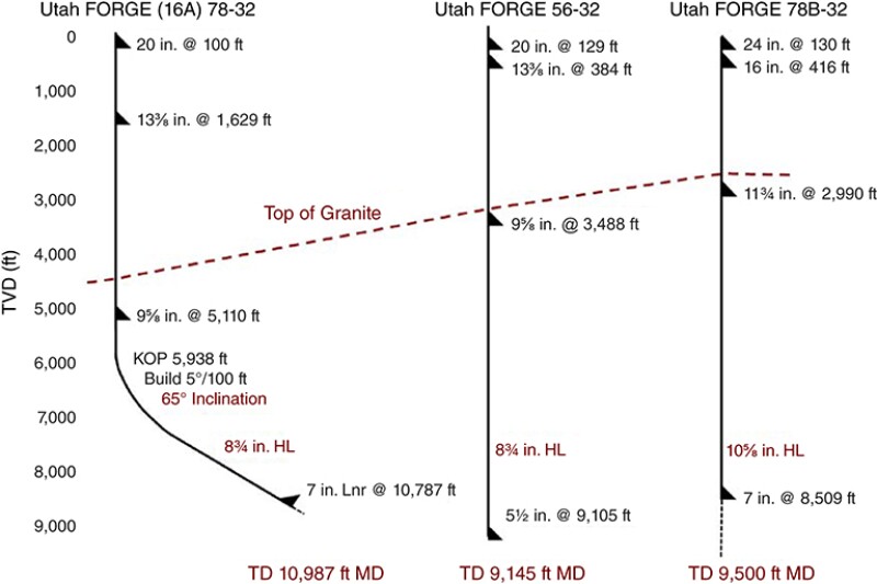
The Texas A&M professors were hired to teach drillers how to cut the time required to drill an injection well and two vertical wells that will observe the impact of fracturing and future water flows (Fig. 1).
Dupriest acknowledged that what is considered fast in shale is far faster than what is possible in hard rock, which he described as “5,000 ft of kitchen countertop.” But he added that “the types of issues that constrain the drill rate, and the way you deal with them, are no different.”
They combined some obvious changes for shale drillers, such as using PDC bits—polycrystalline diamond compact cutters on a solid body that is rotated while drilling—to changing how drillers manage the process by teaching them a “physics-based, limiter-redesign” workflow.
The physics refers to an understanding of the theory. In a perfect world, adding more weight on the bit (WOB) will mean faster drilling. The reality in the ground is that there are limits a driller can recognize using a measure of drilling efficiency—mechanical specific energy (MSE). The MSE data trend plays a critical role in diagnosing what problems are behind the barriers to faster drilling.
Limiter redesign is the process used to diagnose the source of performance limits, or dysfunctions, and find a way to prevent them. Solutions often require reaching out to engineers, suppliers, or experts for advice. For a more complete explanation of the method, see For Further Reading at the end of this article.
Over three wells the drilling team lowered well times by “more than half.” Based on their results, drilling an average of 100 ft/hr was a realistic drilling speed in granite and more is possible. The method also allowed them to extend the life of the bit from a 742-ft run on the first well to a run of 2,100 ft for the last, according to the authors of the paper.
“This well really broke the dam in terms of drilling in geothermal circles because it proved that PDC technology could dramatically improve performance over roller cones [tricone bits],” said John McLennan, Utah FORGE technical lead for resource management and an associate professor of chemical engineering at The University of Utah, which runs the site. He added, “A lot of the credit for this goes to two folks at Texas A&M University, Fred Dupriest and Sam Noynaert.”
A New Bit
Test Well 1
- Name: 16A(78)-32
- Purpose: Injection well
- Depth: 10,987 ft measured depth (MD);
- 8,559 ft total vertical depth (TVD)
- Granite: 6,500 ft
The obvious reason that the rate of penetration (ROP) at the first test well was a lot higher than the previous one was they began using a PDC bit.
The drilling crew managed to set that short-lived record while drilling the deepest well at the site with the most-complex well design—a deviated wellbore that curved off at a 65° angle at about 6,000 ft deep.
The fact that PDC bits have not been widely used by geothermal drillers is one indication of how it differs from oil and gas drilling.
Horizontal drilling technology rapidly improved during the shale revolution, which depended on faster drilling rates to lower the cost of the many horizontal wells needed to sustain its production growth.
In comparison, geothermal drilling is a tiny niche in the business on its own slow-moving path. The focus was less on drilling faster and more on knowing how to solve problems unique to this sector, such as safely drilling while venting steam.
The drillers made do with the equipment available. A rotary table drilling rig was used to drill the pilot well (well 58-32), which is an old design that is still commonly used in geothermal development, said Bill Rickard, president and principal drilling engineer of Geothermal Resources, which was hired to plan and manage the drilling of the Utah FORGE wells.
For the pilot well drilled prior to DOE funding, Rickard tried to apply MSE based on what he had learned from technical papers. While drilling the well, he was told by a graduate student hired to analyze the data that gathering MSE readings “using a torque idler on a rotary chain” was frustrating because the data was “all over the place.”
At that point PDC bits seemed to Rickard like a poor choice for geothermal. “Back in 1980, I first put a PDC bit in a geothermal well; it worked well, but it was a high-dollar tool, and I could drill just as fast with a tricone bit,” he said.
That was a diplomatic way of putting it. He said the PDC bit successfully used on the first test well at Utah FORGE was “the first I had ever run in a hard granitic formation that didn’t come out looking like a bull plug.” In other words, it didn’t end up as a PDC with all its cutters broken off.
Dupriest pointed out that while bits are now built to stand up to abrasive, hard rock, “we’ve also learned how to avoid beating them up, particularly in hard rock.” Based on what he learned from Dupriest and Noyaert during the test, Rickard is using PDC bits on other wells he manages for clients.
Everyone involved with the drilling went through a 16-hour training class taught by the Texas A&M team, covering a workflow based on the “physics of drilling.” How the method is used during drilling can be summarized in one sentence: A combination of drilling faster by maximizing the WOB and maximizing the efficiency of the work and the life of the bit by using the MSE data trend to see when something is going wrong.
MSE offers drillers a surface measure of the force needed to drill through the rock. It is normally somewhat higher than the force needed to break the rock in a lab test because downhole conditions affect drilling. When the MSE rises well above that level, drillers need to figure out the source of the dysfunction.
An important part of the workflow is periodic step tests where WOB is added in 5,000-lb increments until the MSE reading shows signs of dysfunction, which begins with inefficient drilling and can reach a point where it destroys the bit.
When those limits are identified, the drilling teams use MSE and other data to diagnose the source of the dysfunction and look for ways to remove the limiter based on an established list of dysfunctions and their treatments.
The changes that significantly improved performance at Utah FORGE included using larger-diameter drillpipe, requesting design changes of the bit maker, and switching the drilling fluid to water.
The training classes included everyone from drilling managers to rig hands and were designed to persuade drilling teams to work together with the support of managers to apply a method that usually asks them to break some old habits.
The phrase “physics-based” is critical when it comes to persuading those doing and managing the drilling to change their ways.
“We resist change when it doesn’t make sense to us, and don’t resist when it does,” Dupriest said, adding that “because they had a physical understanding of each dominant limiter, they diagnosed dysfunction themselves, identified the change needed, and implemented it.”
Based on the feedback, it appears the students valued what they learned.
“I feel that the training provided by Fred and Sam made a difference,” McLennan said. One sign that students valued the training was “we had people wanting to take it again when they came back to drill subsequent wells,” he said.
Some Adjustments Required
Test Well 2
- Name: 56-32
- Purpose: Vertical observation
- Depth: 9,145 ft total and measured depth
- Granite: 5,645 ft
The second well was drilled vertically, which improved performance by eliminating the need to slow down to slide, rotating the bottomhole assembly to steer.
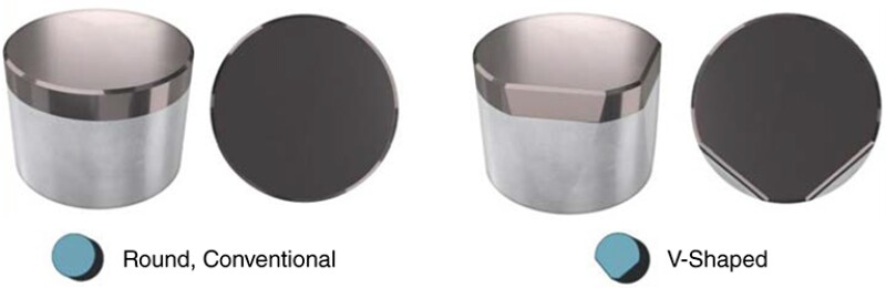
The drilling also benefited from changes made by NOV in the PDC bits. The new design included “v-shaped” cutters designed to indent further into the rock for a deeper cut. This aggressive design reduced the number of rotations required per foot, speeding progress and extending the bit life.
One thing remained unchanged from Test Well 1—the WOB was limited to a range between 35,000 and 45,000 lb, which prevented the assessment of the effect of adding more weight to speed progress. Still, the time on bottom was reduced by one-third from the previous well, and the longest bit run increased by 66%.
Maximizing the Weight
Test Well 3
- Name: 788-32
- Purpose: Vertical observation
- Depth: 9,500 MD
- Granite: 6,000 ft
The third well was also a vertical observation well, but this time, they wanted to see if they could speed the drilling by pushing up the WOB by as much as 50%.
To ensure the rotating drillstring could deliver the torque required at the higher weights without dysfunction, such as sticking and slipping, they increased the drillstring diameter from 5.0 to 5.5 in.
Based on the step tests, they decided they could push the WOB to 68,000 lb, the bit’s structural limit according to NOV.
They drilled faster and extended their record bit run by 70%, providing evidence of Dupriest’s oft-repeated message that more weight could reduce bit wear if the weight added is not causing dysfunction.
The crew did, however, face other problems along the way. While drilling, the MSE readings jumped as high as 85,000 psi— around twice the force required to drill through granite.
After considering several possible causes, they identified drilling mud as the issue. Specifically, at well pressure, the mud compressed the fine granular cuttings together, making them behave as if they were a hard mass and causing a spike in the energy needed to cut and clean the hole.
To prevent the hard masses from forming, they switched to drilling with just water because unlike the mud, water quickly moves among the cuttings, pressurizing those spaces so they have no strength, Dupriest said.
As a result, “ROP doubled and MSE dropped by half as a 100-bbl, freshwater pill passed through the bit,” the paper said.
It is an idea that should be considered in other geothermal wells. In some formations changes will be required, such as using backpressure to ensure well control, said Dupriest, adding that “the prize is large enough to get inventive, if needed.”
Ultimately the gains due to drilling brainpower equaled what was added by the PDC bits. “Even after PDCs were introduced on the first well, the on-bottom drilling time was again cut by more than half through continued changes made by the team,” Dupriest said.
Jody Robins, senior geothermal engineer for the National Renewable Energy Laboratory who is working on a report about drilling costs, was impressed by the fact that “speeds unheard of” in geothermal were reached, where a common average is 10 ft/hr. There were “big jumps” from well to well and “by the third well, they really blew it down,” Robins said.
What’s Next
Unconventional drillers have learned from many thousands of wells, so it is reasonable to assume that there is room for improvement in geothermal drilling after a three-well test.
Adding more weight does not appear to be an option because it would require creating a bit able to handle an even greater load. However, to do that, Dupriest said the bit designer “may need to sacrifice other important features.”
There are other options to consider that he said could potentially increase the drilling speed by 30% in hard rock. Faster rotation could allow greater penetration per foot, but that would require stronger motors and increased fluid flows to prevent overheating the bit.
Another performance limiter, if its cause could be figured out and remedied, is that when drilling with a new bit starts in hard rock, the ROP slows considerably over the first 100 to 200 ft.
“The largest prize is probably to figure out why bits are losing ROP early in the run. Virtually all bits start at around 250 ft/hr, then decline over the first 100 to 200 ft of drilling to about half of that. If a bit drills 1 ft at 250 ft/hr, it should drill every foot of the same rock at 250 ft/hr,” Dupriest said.
It is hard to see how bit wear is an issue because he said “the wear observed is hardly noticeable, and most drillers would still call the bit ‘green.’ It’s likely related to a very small amount of wear, but that wear has to be triggering a very large dysfunction, and it’s the dysfunction we need to figure out,” he said.
Fast Enough?
Faster is better, but are they fast enough to justify developing hot-rock injection projects?
The answer is: They are clearly closer to the target, which at this point is likely to move.
After the surprising gains from these three wells, Robins said they considered whether their baseline drilling cost curve “is not aggressive enough,” and concluded the “baseline is still cheaper than what we can do in real life.”
The costs of faster drilling will be incorporated in the DOE’s Geothermal Electricity Technology Evaluation Model used to evaluate whether this method is at a nearly commercial status. While faster drilling represents a significant saving, it does not affect other completion costs such as fracturing and the casing. As a result, “there are diminishing returns after 50 ft/hr,” he said.
Robins, who has more than 20 years’ oil and gas drilling and completion experience, noted, “If you are coming from the oil and gas side, you do not realize how big the wells need to be” or the large-diameter casing needed to provide adequate flow. Also, nearly every packer and bridge plug they tested in these hot wells has failed, which could be an expensive problem to resolve.
The number of wells required per megawatt generated is not known. In past tests the energy output of each well—based on the volume of water and its heat content—was so low that the number of wells required for a power plant would have been impossibly high.
It will be a while before Utah FORGE can offer any data showing the efficiency of its well pair. It recently fractured the injection well and will be drilling and fracturing the production well in a year with plans based on the recent fracturing results.
For Rickard, the test wells have already changed his approach to geothermal drilling. By teaching the method and using PDC bits, he has reduced the days per well from 50 to as low as 31. At time of writing, he was working on a job that he expected to complete in 25 days.
For Dupriest, recruiting another teacher is a win as he tries to figure out how to pass on his work to the next generation, which includes a large group of students who took his course at Texas A&M.
Rickard hopes it will be a tool to help him pass on what he knows about drilling to those in the eight-person company. “I had been doing that kind of thing my entire career, but it was not nearly as well organized, with not nearly the number of wells and the background that Fred has,” Rickard said, adding, “When you double the ROP over three wells there is a lot to be said for it.”
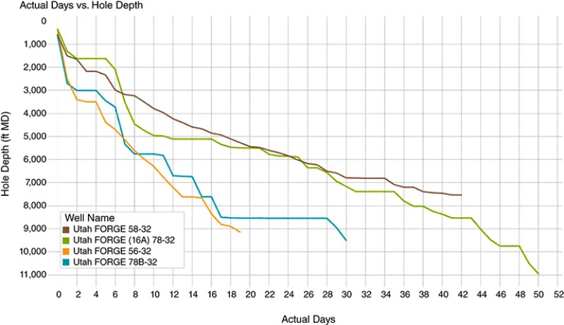
A three-well test at the Utah FORGE site clearly showed it is possible to drill twice as fast through granite. Charts included in the test reports offer a more detailed look at their performance.
![The third test well (788-32) required one-fifth of the time as the first one [16A(78)-32] based on the periods when they were actually drilling](https://assets.spe.org/dims4/default/15614e9/2147483647/strip/true/crop/768x495+0+0/resize/800x516!/quality/90/?url=http%3A%2F%2Fspe-brightspot.s3.us-east-2.amazonaws.com%2F57%2Fa3%2F42c13d6a4b77b35cc6389f63b49e%2Fjpt-2022-06-geothermalseqf1.jpg)
For Further Reading
SPE 208798 Drilling Practices and Workflows for Geothermal Operations by Fred Dupriest and Sam Noynaert, Texas A&M University.
SPE 208777 Standardization of Mechanical Specific Energy Equations and Nomenclature by Fred Dupriest, Texas A&M; Paul Pastusek, ExxonMobil Upstream Integrated Solutions Co.; Stephen Lai and Bob Best, Pason Systems et al.