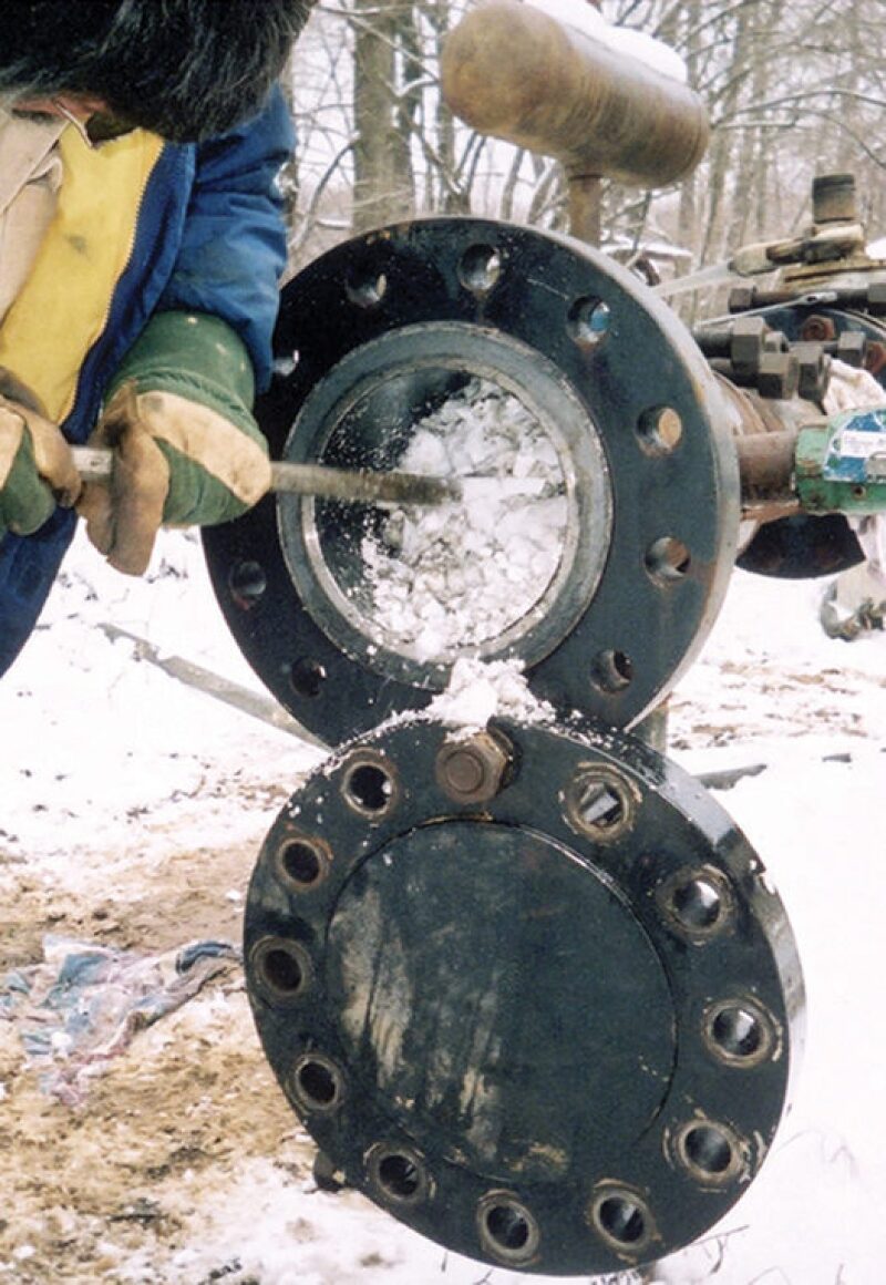
One of the more challenging flow assurance problems in deepwater subsea gas pipelines and equipment is the formation of natural gas hydrates. Gas hydrates form under conditions of low temperatures and high pressures, such as those found in deep water, when ice-like crystalline structures of water form “cages” around low molecular weight gases, especially methane. Methane is the most common trapped gas in hydrates, comprising 99% of the trapped gas. Carbon dioxide, propane, and ethane can also form hydrates.
Hydrates, when formed in sufficient quantities, can form plugs and stop flow in pipelines, flowlines, and equipment and create pressure buildups that could rupture a pipeline.
Achieving effective hydrate prevention not only reduces the risk of the plugging or rupturing of pipelines, but it also can be the key to optimizing the economic threshold of a marginal field.
Methods of Hydrate Prevention
Hydrate prevention methods include reducing the pressure in the pipeline below the threshold pressure at which hydrates form (for a given temperature), insulating or heating the pipeline to maintain a higher operating temperature, dehydrating the gas to reduce the water content and keep the system above the water dewpoint, and inhibition. Traditional hydrate inhibitors, such as methanol or monoethylene glycol (MEG), shift the thermodynamic conditions at which hydrates form. Kinetic hydrate inhibitors, which are polymer-based chemicals, delay the growth of the hydrate.
Thermodynamic inhibition with MEG or methanol is the most widely used method of hydrate control in deepwater production systems. The selection of MEG or methanol involves comparison of factors including capital and operating costs. A main consideration is whether the spent chemical will be recovered, regenerated, and reinjected. MEG is normally recovered and recycled, whereas methanol is used in once-through systems and, in some cases, is partially recovered. Because the solubility of methanol in gas is greater than that of MEG in gas, the high loss of methanol into the gas increases the operating cost for chemical makeup in once-through methanol systems, especially in cases of high gas production or large volumes of produced water.
Although the solubility loss of MEG into the sales gas is negligible and loss to the liquid hydrocarbon phase is low, the use of MEG also has its challenges, of which salt (sodium) contamination from seawater is at the top of the list. Because water is more volatile than MEG, the salts remain behind in the glycol phase during regeneration. To avoid salt precipitation and plugging problems in equipment, it is necessary to remove salts from the MEG solution before reinjection. Recovery rates of MEG need to be maximized to reduce chemical costs and optimize the economics of the project.
Independence Hub’s MEG Reclamation Process
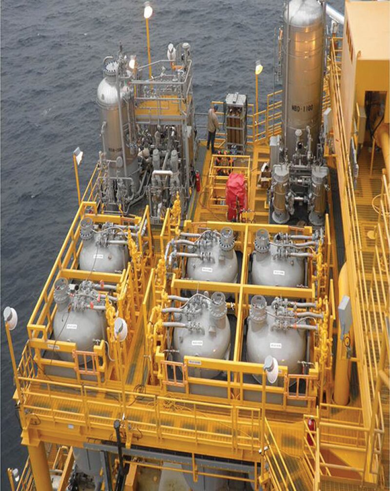
Independence Hub, the largest natural gas processing facility in the Gulf of Mexico, began producing in 2007. The project, operated by Anadarko Petroleum, spans 1,800 sq miles and during the first quarter of 2012, its cumulative gas production surpassed 1 Tcf. Independence Hub contains the world’s largest offshore MEG reclamation system with a feed capacity of 7,800 B/D of rich MEG. (MEG contained in produced water is called “wet” or “rich.” After the MEG is reclaimed, it is referred to as “dry” or “lean.”)
Bob Buck, Gulf of Mexico production engineering manager with Anadarko, said MEG was selected for hydrate control at Independence Hub for several reasons. Gas composed of about 98% methane is produced from wells at 8,000 ft water depth, where the conditions of low temperature and high pressure result in the formation of Type 1 hydrates. Low dose hydrate inhibitors for Type 1 hydrates were not available at the time of startup. The daily methanol requirement would have been 180 B/D—far too costly for one-time use and disposal.
Anadarko selected Cameron’s flash vaporization process for MEG reclamation (Fig. 1). Unlike oil and water, which have significantly different densities that allow the use of gravity separators, MEG and water densities are miscible and, thus, gravity or enhanced gravity separation processes cannot be used. Flash vaporization is required for separation, Buck said.
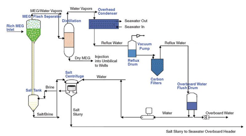
The flash separator is operated in a vacuum at 3–4 psia, Buck said. Because MEG boils at 380°F, but degrades at 320°F (standard conditions), a vacuum is used to lower its boiling point to 275°F to prevent degradation but still achieve vaporization of the MEG.
The incoming stream of wet MEG enters the flash separator, where the wet MEG and water are flashed off with their vapors exiting from the top of the flash separator. When the MEG and water vapors next enter the distillation column, MEG condenses first and becomes a liquid. The reclaimed, or lean, MEG exits the bottom of the distillation column and goes to the lean MEG tank, where it is held until reinjected into the topsides umbilical termination assembly for distribution to the subsea wells. The water vapors go from the distillation column to an overhead condenser, and the resulting distilled reflux water goes to a reflux drum where it can be used in the topside reclamation process or discharged overboard as the distilled water meets the US Environmental Protection Agency’s National Pollutant Discharge Elimination System discharge requirements.
During the flash vaporization process, the salt crystals form in the flash separator and eventually settle out. Reflux water is added to the salt brine where the mixture is centrifuged to yield clean salt. The clean salt can be sent to shore in tanks or may be clean enough to dispose of overboard once appropriate regulatory approvals are obtained.


|
Lessons Learned in MEG Reclamation
In the course of running a large-scale MEG reclamation process, Anadarko encountered unexpected challenges. “One of the first problems identified after we went on production was the appearance of an API°18 gravity oil produced by the wells. Based on our early tests that showed API°40 gravity condensates, we were expecting a light condensate,” Buck said.
The combination of oil- and water-soluble organics complicated complete separation of the hydrocarbons from the wet MEG feedstream. Oil entered the flash separator, where its light ends (low-molecular-weight fraction) flashed off, and the heavy ends (nonvolatile, high-molecular-weight fraction) were carried out to the distillation column and into the lean MEG tank. The tar-like deposits were found on the topside MEG injection filters and on the filters of the SkoFlo valves. (SkoFlo valves are flow control valves used to distribute chemicals from a common umbilical to each subsea tree). Buck said, “These tar-like deposits were bypassing the filters and getting into the umbilicals, which impeded MEG injection to the wells.”
Attempts at filtering upstream of the flash separator to separate the oil and grease from the wet MEG failed to yield clean, dry MEG. “So we installed oil-absorbent sock filters in the downstream filter pots to remove the oil and grease from the dry MEG,” Buck said.
Upstream separation and filtration is used to remove as many hydrocarbons as possible from the incoming stream to the flash separator. Anadarko uses a three-phase separator, cartridge filters, a horizontal flotation system, and a series of carbon filters, each 7 ft diameter by 12.5 ft high. Even with this robust separation system, the tar-like hydrocarbon deposits still occasionally enter the umbilicals and reach the SkoFlo filters. Pressure gauges up- and downstream of the SkoFlo valve filters monitor the pressure differential and provide an indicator of flow impediment, triggering the injection of xylene into the umbilicals for delivery to the SkoFlo valve filters. Buck said, “Fortunately, xylene removes the hydrocarbon deposits and restores full injectivity.”
The calcium chloride in the incoming MEG and produced water presents another challenge for which Anadarko is continuing to seek solutions. The calcium chloride enters the flash separator along with the MEG. While the water flashes off and the salt drops, the calcium chloride remains soluble in the MEG. As the volume of produced water increases, more calcium chloride accumulates in the MEG and increases the viscosity of the fluid in the flash separator. When fluid is pulled from the bottom of the flash separator to be recycled through heaters and pumped back to the flash separator as a means to maintain its high operating temperature, the increased viscosity of the fluid is problematic.
Buck said, “When you pump this increasingly viscous fluid, you’ll eventually max out your pump amps, at which point you must shut in and drain the entire flash separator, refill it, and resume operations. That is the method currently being used to remove the soluble calcium chloride in the flash separator.
“We proactively pull off about 50 to 100 bbl of fluid from the flash separator intermittently and replace that volume with clean MEG. But eventually, the fluid reaches a level of viscosity where draining of the flash separator is required.”
Anadarko is seeking a means for controlling the amount of calcium chloride that enters the flash separator. Buck said, “We can precipitate out the calcium chloride as calcium carbonate and then separate out the solids by using a properly selected centrifuge or filter; the problem is capital cost of the equipment and the operating cost associated with bringing the chemicals on board as a retrofitted project. Due to a decline in the calcium levels, we did not pursue that any further.”
Buck said that testing of an ion exchange unit has been shown to be effective at removing the calcium chloride. “The problem was identifying the best time for regeneration of the media. We did not have a reliable means of measuring calcium chloride in the MEG. Detection kits work well in water, but do not work in MEG, and analytical methods such as titration are not practical for crews working on offshore platforms.”
For Further Reading
OTC 18010 Advances in Glycol Reclamation Technology by C.A. Nazzer, Prime Services Ltd., and J. Keogh, Petreco Intl.
OTC 19518 Mitigating Flow Assurance Challenges Using Subsea Meters on Independence Hub by Nikhil B. Joshi, Moulinex Business Services, and Bob Buck, Anadarko Petroleum
OTC 20338 Pioneer Challenge Reduction of MEG Consumption Using KHI for Hydrate Control in a Deepwater Environment Offshore Egypt by Fawaz Abdel Latif Agizah, Taher Abdel Raheem Ali, Rashid Petroleum Company, et al.
OTC 22487 A Novel Technique for Optimising Hydrate Inhibitor Injection Rates by Saeid Mazloum, Antonin Chapoy, Institute of Petroleum Engineering, Heriot-Watt University, et al.
OTC 23490 Predicting Hydrate Blockages in Oil, Gas and Water-Dominated Systems by L.E. Zerpa, Z.M. Aman, Colorado School of Mines, et al.