

Fluid samples collected using either wireline or logging-while-drilling (LWD) formation-testing technology for reservoir fluid characterization have long been accepted as the most representative of reservoir fluid. This, though, comes with a caveat that the collected sample is clean and devoid of any mud-filtrate contamination. With both techniques performed soon after drilling a well, there is always a risk of contaminating the collected fluid with mud filtrate.
Toward the goal of reducing this risk, since the early 2000s, technologies have been brought forth to help identify the fluid down hole. There have been multiple developments with sensors for absorbance spectroscopy, fluorescence, fluid resistivity, fluid refractive index, and so on. Each sensor development was targeted toward a specific fluid interaction with the mud filtrate, thereby helping to differentiate the reservoir fluid from the mud filtrate.
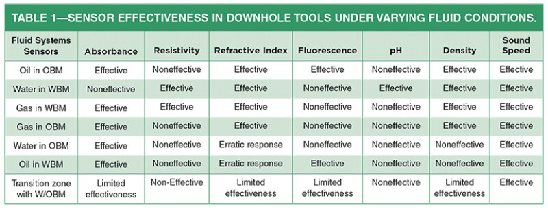
Downhole sampling conditions can be classified into two broad groups: one case where the reservoir fluid is miscible with the mud filtrate and the other where the reservoir fluid is not miscible with the mud filtrate. The immiscible cases are generally straightforward, since sensors such as absorbance spectroscopy can easily differentiate among oil, water, and gas. In addition, the technique can be used to determine the fractional portion of each phase in the flow. Complications arise when the reservoir fluids happen to be miscible with the mud filtrate system; for example, while sampling reservoir water in the presence of water-based mud filtrate, absorbance spectroscopy by itself is unable to differentiate among the fluids.
Table 1 provides generic information about different fluid systems as well as the sensors used to differentiate the fluids. While there are other sources of correlation-based fluid-property information, the basic sensors mentioned are the ones used for correlations. As mentioned, each sensor provides detailed information for specific cases, but only sound speed provides a single-sensor solution for the conditions expected.
Sound-Speed (SS) Measurement
While acoustic data have long been used for reservoir characterization, data have been used for fluid characterization during downhole sampling for only a decade. Experience has shown that this measurement is sensitive enough to not only differentiate injection water or formation water but also to track and quantify small changes in oil compressibility—an important step in focused sampling. The measurement uses a pulse-echo technique based on the principle that an acoustic signal propagates approximately as a plane wave, and that the speed of sound is based on the distance the pulse travels divided by the time it took to traverse the distance. (SPWLA-2013-FFF).
The 10-MHz piezoelectric transducer is mounted onto a machined flat surface on the flowline of RCX (the wireline formation testing tool reservoir characterization instrument) as schematically shown in Fig. 1. The travel path length is the distance between the two internal surfaces of the flowline. The result was a bulk measurement of the speed of sound across all the fluid flowing though the flowline. The only calibration needed is for this path length, which can differ due to slight machining variations. A calibrated sensor was able to differentiate fluids which exhibited sound-speed differences as small as 4.7 m/sec (0.5 msec/ft of sound-speed slowness).
Fluid Sampling Under Different Conditions
Sampling formation oil in the presence of oil-based mud (OBM) filtrate. This condition is especially encountered during the exploration phase, as represented by a job performed with a focused sampling tool that resulted in a shorter cleaning time (green curve in Fig. 2). The jump in sound-speed slowness around the 1,500-seconds mark (first shaded green oval in Fig. 2) is due to the focusing effect. Thereafter, the changes are very subtle (second shaded green oval in Fig 2). To capture an ultraclean (negligible/no measurable amount of filtrate contamination) sample, these subtle changes are essential as they indicate small changes in the amount of contamination still present.
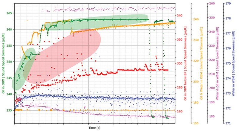
Sampling formation water in the presence of water-based mud (WBM) filtrate. The blue curve in Fig. 2 is an example of the effectiveness of the sound-speed measurement. Most sensors designed for differentiating water have severe limitations in the salinity differences needed to distinguish the two, since each sensor has its own limit. The sound-speed slowness method, with its ability to differentiate fluids with differences as small as 0.5 msec/ft, can differentiate salinity changes as small as 5,000 ppm, as was the case during this job. The added complexity was in identifying the formation water as injection water (from a nearby injection well) or native formation water, as this would directly impact estimations of recovery and reserves. The ease with which this measurement could directly calculate accurate total dissolved solids (TDS) helped to differentiate the injection water, which had a lower TDS, from the formation water (SPE 192320).
Sampling in a transition zone with any mud system. In transition-zone sampling, two different scenarios can be encountered such as formation oil and water in the presence of either OBM filtrate or WBM filtrate. An example of the first scenario is shown by the orange curve in Fig 2. In this case, although the major fraction of flow was oil, the presence of a small amount of water (water sound-speed slowness close to 173 msec/ft) was important for the operating company so as to avoid perforating close to that depth to delay water ingress during production. The changes in the oil sound-speed slowness were tracked at the same time to ensure clean reservoir oil was captured along with the small amount of water. The other transition-zone-sampling example (shown in magenta in Fig. 2) represents the formation oil-and-water sampling in the presence of WBM filtrate. In this case, due to the salinity difference, the sound-speed slowness of the water part of the flow showed changes and was tracked until it stabilized. At the same time, the sound-speed slowness indicated that oil was continuously changing, proving that the measurement was not influenced by the presence of water. A fraction of oil was also monitored, and a sample was captured only after the fractional flow of oil and water was consistent for a period of time. This provided information about the water cut from the formation at the measured flow rate, which aided in the completion design for that well.
Sampling formation oil close to bubblepoint pressure. Fluid sampling with wireline or LWD formation testing technology has been accepted as the best method due to the ease of collecting samples close to their in-situ condition, in single phase, and bringing them to the surface. This can in time become challenging when the formation pressure of a hydrocarbon is close to its bubblepoint/dew point. Care should be taken to make sure that the pressure does not drop below these critical points. While most sensors need a significant quantity of gas to indicate the pressure has dropped below these critical points, the sound-speed sensors respond quickly due to phase changes. At phase changes, the compressibility changes rapidly and it influences the sound-speed measurement (as seen by the red curve in Fig. 2). At close to 4,000 seconds, there is an increased slowness in some of the measurements, which appear as scatter points above the overall changing trend (highlighted by the red oval shape in Fig. 2). This was due to the drop in flowing pressure below the bubblepoint. Progressing further in the job, the pressure drop was reduced, and the gas signals disappeared.
While it is always recommended to use all the sensor responses during downhole fluid identification, the sound-speed measurement offers critical insights in cases where fluid property changes are very stable and may be beyond the resolution of other sensors. Strong correlation for determining TDS in water across a wide range of dissolved solids as well as correlation for gas/oil ratio determination enhance the importance of this unique measurement.
For Further Reading
SPWLA-2013-FFF Validation of Downhole Fluid Density, Viscosity and Sound Speed Sensor Measurements by Y. Liu, R. DiFoggio, A. Hunnur, P. Bergren, and L. Perez, Baker Hughes.
SPE 192320 Estimation of Typical Total Dissolved Solids in Water from Downhole Ultrasonic Sound Speed Formation Tester Survey by V.S. Torlov, and O.M. Akinyose, Saudi Aramco; and A. Amin, Baker Hughes GE.

Anup Hunnur is a global advisor for formation testing and sampling at Baker Hughes Company in Houston. In this role, he provides technical support, mentoring, and trainings in all aspects related to testing and sampling. He has been with the company for 15 years and has experience working around the world. Hunnur holds an MS degree in petroleum engineering from The University of Oklahoma and a BE in chemical engineering from Bangalore University, India.