The designs used for the first stages fractured at the Utah FORGE test site are going to look a bit odd to those doing plug-and-perf jobs on oil wells.
The first stage was a 200-ft-long openhole section. That sort of frac was tried and dropped early in the evolution for shale oil and gas because it didn’t deliver enough production to justify the effort.
For the second stage only slickwater was pumped into a cased stage to fracture a single cluster—a big one with 120 perforations concentrated in a 20-ft section of wellbore.
The third stage also used a megacluster. Like the second, it was pumped at 35 bbl/min, which is lower than the rates commonly used to fracture a typical shale well. What was different was that the fluid included gel and fine grains of microproppant.
Those stage designs are not like those done in shale, but the geothermal test site in Utah is designing experiments that will hopefully lead to a better understanding of how to apply a familiar technology toward achieving an unfamiliar end.
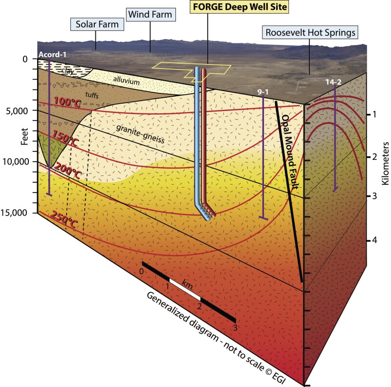
Backed by $220 million from the US Department of Energy, the Utah FORGE team’s goal is to develop the techniques and tools needed to create well-to-well flow paths through rocks that are at more than 400°F and then send the heated fluids to the surface to power electric generation. This approach is known as an enhanced geothermal system (EGS).
To create those conductive pathways “we want to have frac hits,” said John McLennan, a chemical engineering professor at The University of Utah and co-leader on the Utah FORGE project which is managed by the university.
The years of work they have done prior to fracturing three stages at the end of the injection well shows it is more difficult than that short description would suggest.
The site includes several heavily instrumented wells to image the fractures after stimulation. These images will guide where the production well is placed, which will be 300 ft away from the injection well and deviated at a 65° angle.
That is far closer than the wells will be if this technology ever goes commercial, but at this early stage the goal is to gain a fundamental understanding of how fracturing works in hot granite.
Based on what is being learned from those first three stages, they are trying to figure out what sort of fractures are created in granite by pressure pumping, where those fractures go, and if there is a way to create the flow paths needed.
And most importantly, determining if it is possible to inject cold water into one well and produce really hot water from another.
“We will hopefully be able to pump into the injection well and establish communication,” McLennan said. “There may be some additional stimulation treatments pumped in the production well to create additional hydraulic fracture connections to the injection well—but that is yet to be determined.”
It has taken years to get to this point. The painstaking approach reflects a previous test at Fenton Hill in New Mexico back in 1983 where two wells were drilled and fractured and not much water flowed from one to the other.
Predicting Fracture Growth
Scaling up geothermal power generation based on water injection into hot rock will require finding a way to predictably deliver the right sort of fractures. While shale grew using “pump and pray” fracturing methods, investors are not going to put up billions to develop EGS plants unless the subsurface heating systems can be dependably manufactured.
For now, the questions are more basic. A big one is: What do the fractures look like after pressure pumping? Are they long and straight planar ones or tight, complex clusters?
“One of the real uncertainties is what the morphology of the fractures will be,” McLennan said.
They also need to find out if they are fracturing the granite or expanding the fractures already present around the well.
A better understanding of fracture growth is needed to develop models that simulate how different approaches will play out, which will make it possible to test new ideas in a computer rather than in the ground.
“The simulations we have done are showing we do not really know what these natural fractures will do,” McLennan said, adding that the recent work “provides the data to more clearly constrain” the algorithms used for the simulations.
A paper recently presented at the SPE Hydraulic Fracturing Technology Conference highlighted the problem. The reservoir modeling firm ResFrac offered examples of what can be done to understand geothermal fracturing systems, but said it is not yet possible to model a well plan for a specific location (SPE 209186).
“The modeling process illuminates key gaps in knowledge,” the authors wrote. “We need more information about the size, direction, shape, and mechanism of stimulated fractures created from multistage stimulation in igneous/metamorphic rocks. We also need measurements of the field-scale propped and unpropped fracture conductivity.”
Hitting Natural Fractures
Based on the early data, the fracturing test went smoothly. When the treating-pressure charts were compared to the results from two fracture diagnostic tests run prior to fracturing—a diagnostic fracture-injection test (DFIT) and a shear-stimulation test—it appeared that pressure pumping was extending existing cracks.
“The relatively smooth changes in the treating-pressure charts suggested the fluid was flowing into natural fractures and expanding them rather than breaking down the rock,” said Kevin England, the consulting engineering who was the senior advisor on the test.
The pressure response as they stepped down the pumping rate after reaching a peak level indicated “there was not a fundamental change in geometry” of the fractures, he said.
The response suggested that this high-tensile-strength rock will deform when pressured rather than break.
The chart for the second stage shows a sharp pressure drop, which was caused by an intentional shutdown of the pumps for another pressure test done during the fracturing.
They placed the fractures based on where they’d seen indications of natural fractures in sonic and microimaging logging done during drilling, England said.
“We wanted to make sure that the initiation of fracture was not problematic,” McLennan said, adding “It is high-tensile-strength rock, so fracturing may be opening up natural fractures, and if they are not there, then breakdown will be particularly difficult.”
Utah FORGE sent out a statement that described the fracturing test in detail.
On the first stage they pumped 4,261 bbl/min of slickwater into the 200-ft-long openhole section located below the casing shoe. The pumping rate started at 5 bbl/min and increased in 5-bbl/min increments to a peak of 50 bbl/min.
They included the openhole approach which is used in traditional geothermal wells where there is naturally occurring water and highly permeable rock. In this test, they are comparing how it performs compared to perforated casing which directs the pressure to small spots.
The next two stages used a plug-and-perf design with a 20-ft-long megacluster placed to take advantage of short sections with a concentration of fractures—either natural or created while drilling.
They originally planned to hit a 10-ft-long section but decided to double the cluster to 20 ft and 120 perforations to make sure they hit the area in a well where the electronic tools normally used to measure the well depth while running tools were not available due to the heat.
They expected that with all those shots, a few fractures would grow long.
“The rationale is that a hydraulic fracture will initiate at the lowest point of stress within the 20 ft that is perforated and preferentially where there are pre-existing weaknesses [such as natural or induced fractures if they are present],” McLennan said. “It is possible that more than one hydraulic fracture could initiate in each cluster, but with interacting pressure/stresses between fractures, only one or possibly two would continue to propagate into the formation.”
They were trying to create conductive fractures but also ones that created a clear signal that allowed them to test their ability to image. To prevent overlapping signals, the two clusters were placed 460 ft apart.
The fluid varied among the stages. The first and second stages used slickwater—fresh water with a limited amount of friction reducer They pumped 2,777 bbl of fluid in the second stage and 3,016 bbl of crosslinked gel in the third where they also pumped microproppant—3 lb/gal early, then dropping to zero before the end of the stage to avoid leaving ceramic grains in the wellbore.
The helical array of perforations will send high-pressure streams of water in six different directions, each 60° apart. From there the high-pressure streams of water will follow the path of least resistance.
A lot of those fractures will go away from the production well. While not contributing to the flow on this test, in the future this data could be used to help design groups of injection and production wells that minimize the number of injection wells needed.
The pumping rate for the two cased stages at Utah FORGE peaked at 35 bbl/min, which was limited by equipment ratings that were reduced by well temperatures of around 435°F.
On the other hand, the wide casing (7-in. OD, 5.92-in. ID) reduced the energy lost by pipe friction, England said.
Even at these pumping rates, the downhole pressure approached the 8,000-psi pressure limit for surface equipment, whose rated capacity is reduced due to the high temperature, England said
The heat also explains why bridge plugs were used to isolate the stages instead of packers. Packers are widely used because they cost less to buy and set via wireline and can be drilled out afterwards.
The plug made and installed by Interwell was a win for the Utah FORGE team which tried and destroyed most of what they had tested. While the bridge plug did the job, they are continuing to search for an isolation device rated for higher temperatures that can be set using a wireline rather than a drill rig, England said.
The next step will be drilling the production well in 2023 based on where the fractures grew. Their goal is to intersect the fractures they have imaged.
“If during the drilling of the production well we are able to intersect the hydraulic fractures created during the stimulation treatments in the injection well, we will hopefully be able to pump into the injection well and establish communication” McLennan said.
If not, “There may be some additional stimulation treatments pumped in the production well to create additional hydraulic fracture connections to the injection well—but that is yet to be determined.”
For Further Reading
SPE 209186 Optimization and Design of Next-Generation Geothermal Systems Created by Multistage Hydraulic Fracturing by Mark McClure, Charles Kang, and Garrett Fowler, ResFrac Corporation.
A description of the three stage test.
Data from Utah FORGE tests at the injection well (16A(78)-32.