The general industry perception is that, when drillstrings or casing strings exceed conventional helical-buckling criteria, they cannot be operated safely in the hole because the risk of failure or lockup is too high. However, some theoretical, experimental, and field case studies have shown that a tubular may be run in the hole even in a buckling state within safe limits.
Introduction
Buckling occurs when the compressive load in a tubular exceeds a critical value, beyond which the tubular is no longer stable and deforms into a sinusoidal or helical shape. Sinusoidal buckling corresponds to a tube that snaps into a sinusoidal shape, and it is sometimes called lateral buckling, snaking, or two-dimensional buckling. Helical buckling corresponds to a tube that snaps into a helical (spiral) shape.
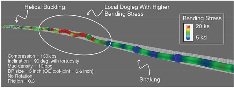
Recent studies have shown that the conventional sinusoidal- and helical-buckling criteria are accurate only in a perfect wellbore geometry because wellbore tortuosity and doglegs play a great role in the buckling phenomenon. An example is illustrated in Fig. 1, which shows that sinusoidal and helical buckling take place simultaneously despite the same compression; doglegs and tortuosity play an important role in the onset of buckling.

Compression on the drillpipe is maximal when tripping in, running casing/liner, or performing slide drilling. Buckling may also occur when drilling with a rotary assembly with a large weight on bit (WOB). The critical helical-buckling load for a rotating pipe may be approximately 50% less than that obtained for a nonrotating pipe. The helical-buckling load is generally the load used in drillstring or casing design to define the limit upon which the tubular might be fully buckled, with the risk of getting stuck or with the risk of large bending stresses that may lead to failure. During well planning, if the compression in the drillstring exceeds the critical helical-buckling load, drilling engineers usually modify the drillstring design until this buckling does not occur. It is widely recognized that sinusoidal buckling is not harmful to a tubular, but helical buckling is generally perceived as a dangerous situation.
Unconventional Plays—Bakken Wells
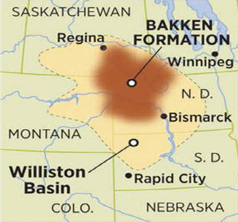
Williston basin’s Bakken field (Fig. 2) is one of the largest unconventional oil-shale resources in North America. Typical well design is to drill a 10,000-ft vertical section, drill a short build section (up to 10–15°/100 ft dogleg severity), set the 7-in. casing, and then drill a 10,000‑ft lateral section. The biggest drilling challenge has been the drilling of the long horizontal section and setting the 4½-in. liner. These well trajectories also have revealed the limitations of current buckling models used by the drilling industry.

Case Study. Six wells were studied in this paper—Wells A, B, C, D, E, and F. Wells A, B, and C show a strong 3D turn during the build section, and Wells D, E, and F almost stay within the same vertical plane. Maximum dogleg severity reached in the build curves ranges from 12.8 to 17.2°/100 ft, and lateral-section lengths vary between 8,955 and 10,724 ft.
Drilling. A 5⅞-in. polycrystalline-diamond-compact bit coupled with a steerable-mud-motor bottomhole assembly was typically used to drill the Bakken formation. The drillstring consisted of 4-in. drillpipe and heavyweight drillpipe. Drilling operations with the steerable mud motor were conducted with an oscillation tool that oscillates or rocks the drillstring to the left or right to reduce axial drag. Instead of generating an axial drag while sliding, friction occurs along the tangential direction (torque) because of the oscillation from the surface. This technology has been shown to be effective in improving slide-drilling efficiency. The torque modeled is pretty close to the actual measurements, even though some torque fluctuations are observed. Those fluctuations, however, are mainly caused by actual WOB fluctuations. According to conventional helical-buckling criteria, helical buckling might occur between 9,000 and 9,600 ft. However, according to the authors’ buckling modeling, no helical buckling is observed during drilling along the drillstring and a maximum WOB of 20,000 lbf can be applied safely.
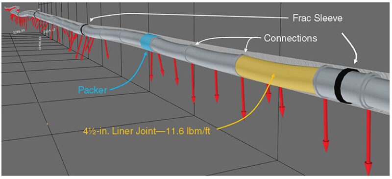
Running 4½-in. Liner. The lateral sections of the six wells were completed with 4½-in. swellable-packer completion systems. Packers, liners, and fracture sleeves were thoroughly modeled, as seen in Fig. 3, where one can see that detailed components have been entered to model their effect. Indeed, accurate torque-and-drag modeling of the completion string requires a good knowledge of the linear weight, inner and outer diameter, and gauge/connections outer diameter of each element to take into account the stiffness effect better and calculate contact side forces more accurately. In Fig. 3, red vectors represent the contact side force between the tubular and the borehole (mainly on the lower side, in this example). Fluctuations in actual hook-load data (approximately every 2,000 ft) of Well B correspond to the partial fill-up during the operations. Even though the rock formation, completion strings, and trajectories in these wells are very similar, the difference in friction may come from the unknown borehole tortuosity between two consecutive surveys (generally 100 ft apart) and also from the actual data quality and calibration (five different rigs). The torque-and-drag model has reproduced the actual hook-load tendencies for these wells. More importantly, these simulations demonstrate that, in some sections, helical-buckling loads have been exceeded without compromising the operation success. Indeed, during the running-in-hole operations of the five completion strings, helical-buckling load was largely exceeded for more than 6,000 ft in the lateral section. In Well B, the conventional helical-buckling load begins to be exceeded at approximately 14,000 ft and is largely exceeded at 20,561 ft. When the string is at 20,561 ft, the compression in the completion string is even four times the helical-buckling load at a depth of 10,000 ft. Even though this situation could seem dangerous, stress analyses within the tubular show that the bending stresses remain at an acceptable level in the buckled zone.

A buckling-severity index has been proposed that focuses much more on the state of the tubular stress than on the buckling shape. This index is based on the bending stress, the contact side force, and the von Mises stress and is ranged from 1 (low risk) to 4 (severe risk). For Well B, a medium buckling risk has been estimated for the running-in-hole operation, showing that the operator was right to continue running in hole even though standard helical-buckling criteria were exceeded. In Well C, a buckling-severity index of 3 was reached at approximately 9,300 ft, the depth at which a failure occurred in the liner (the compression reached 80,000 lbf). Even though it is extremely difficult to predict the occurrence of a failure, this index provides some early warning on potential troubles.
Summary and Conclusions
- Torque-and-drag data from Bakken field in North Dakota have been gathered, analyzed, and compared to an advanced drillstring model and post-buckling simulation.
- Field results supported by the torque-and-drag model suggest that some parts of the drillstrings exceeded the helical buckling criteria during slide drilling and liner running. Numerical-simulation results indicate acceptable bending stress, and, thus, the operations can continue.
- One should be cautious that the clearance between the tubular and the wellbore plays a significant role in bending moment. As long as the wellbore is not overgauge, the numerical model suggests that bending moment created by doglegs sometimes can be higher than that from helical buckling.
- In rotary drilling, buckling should be avoided because it will create high vibrations. The effect of dynamics or vibrations was not included in this study.
- Without considering the effect of vibrations, the bending stress in most operations remains at an acceptable level (buckling-severity index less than or equal to 2). The only liner failure occurred when the buckling-severity index reached 3 (high risk). Thus, a buckling-severity index equal to or greater than 3 requires particular attention and monitoring.
This article, written by Editorial Manager Adam Wilson, contains highlights of paper SPE 163518, “Safely Exceeding Buckling Loads in Long Horizontal Wells: Case Study in Shale Plays,” by S. Menand, SPE, DrillScan, and D. C-K Chen, SPE, Hess, prepared for the 2013 SPE/IADC Drilling Conference and Exhibition, Amsterdam, 5–7 March. The paper has not been peer reviewed.
